IPC-TM-650 Coupon Testing
USING THE OM THERMAL STRESS SYSTEM
Printed circuit boards (PCBs) are vitally important for a wide range of products. Class 3 PCBs are especially important since they are designed to meet the stringent requirements of military, medical and aerospace applications. PCB testing at the bare board level is crucial to ensuring printed circuit board assembly (PCBA) quality.
When testing is not performed at the bare board level you can be at risk of field failures or board power failures, which can lead to thousands of wasted components. However, when testing is performed at the bare board level, manufacturers can detect defects early on before final product assembly, minimizing time, money and labor.
The structural integrity and internal electrical connections of a PCB are best tested using a test coupon. A test coupon is a small piece of a PCB panel that is not intended for use, but is reserved for destructive analysis. Since they are produced at the same time as the rest of the PCBs, coupons have the same dimensions and electrical properties, including trace widths, spacing and impedance values.
Using the OM Thermal Stress System, we can perform convection reflow assembly simulation and/or thermal shock in a single chamber. A single load consists of twenty-four (24) D coupons or more than twenty-five (25) A/B coupons. Data acquisition for D coupons is unmatched, with 4-wire precision resistance reading per net per second! Once testing is complete, a technical report is produced that includes reflow and/or thermal shock profiles as well as resistance change data for each coupon.
Although a variety of test coupons are available for testing, only A/B and D coupons are covered below.
- An IPC-2221 A/B coupon allows inspection of both vias and component holes. Typically the outer row of the coupon is considered the A coupon which enables rework simulation for component holes. This coupon usually contains larger holes. The inner row of the coupon contains coupon B, which assesses the thermal stress of plated-through holes. This coupon usually contains smaller holes. The purpose of this coupon is for plated hole/via evaluation, feature size and spacing, registration, thermal stress and rework simulation.
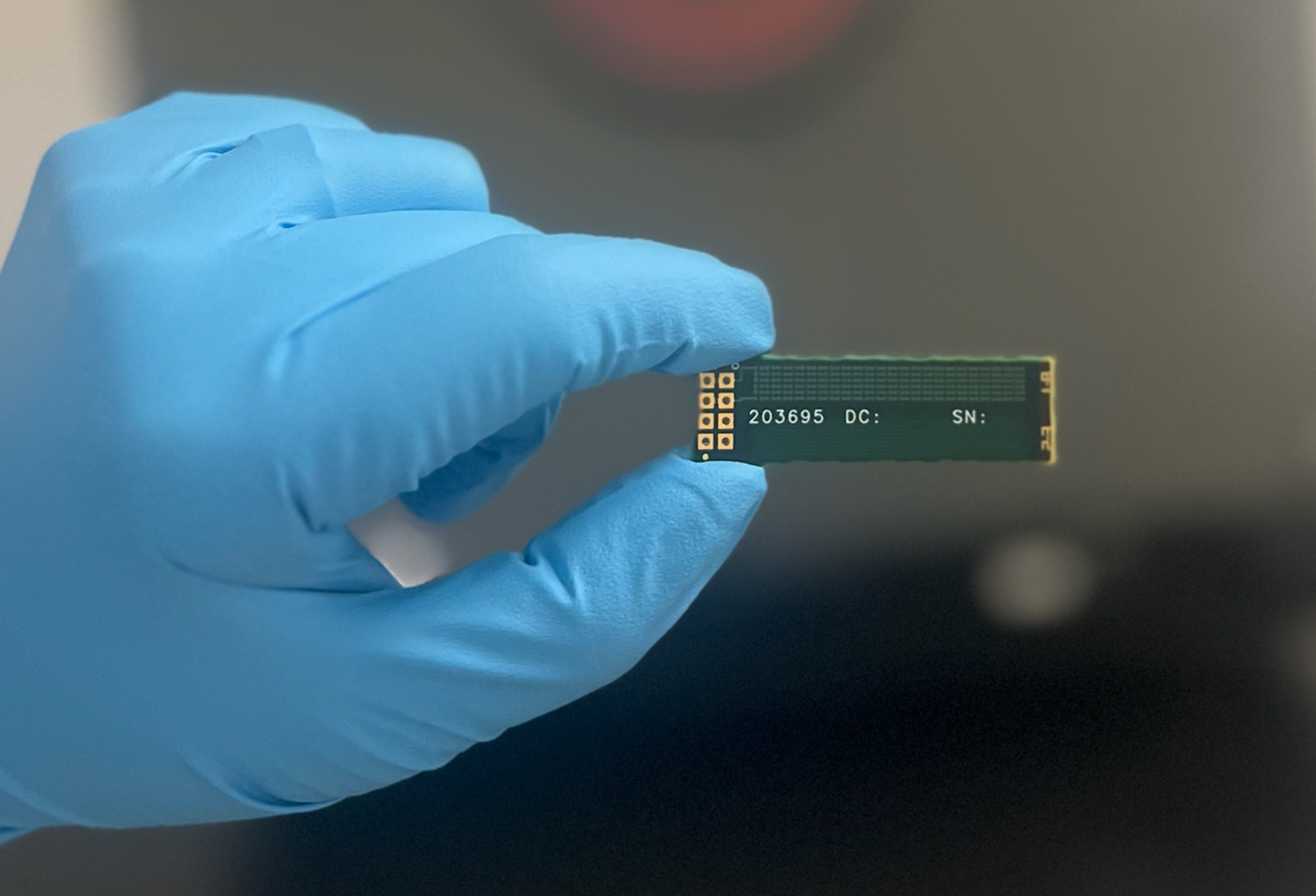
- An IPC-2221 D coupon allows interconnection resistance, continuity and stack-up. Structures are formed by combining two or more unique vias. For precise resistance measurements, nets are formed by replicating vias or structures into a daisy-chain. D coupons contain two nets representing component holes or via structures. The purpose of this coupon is to evaluate plate-hole and via reliability by thermal stress. Refer to figure 1 for example.
Contact us for information about coupon testing
Fig. 1 Typical D Coupon layout
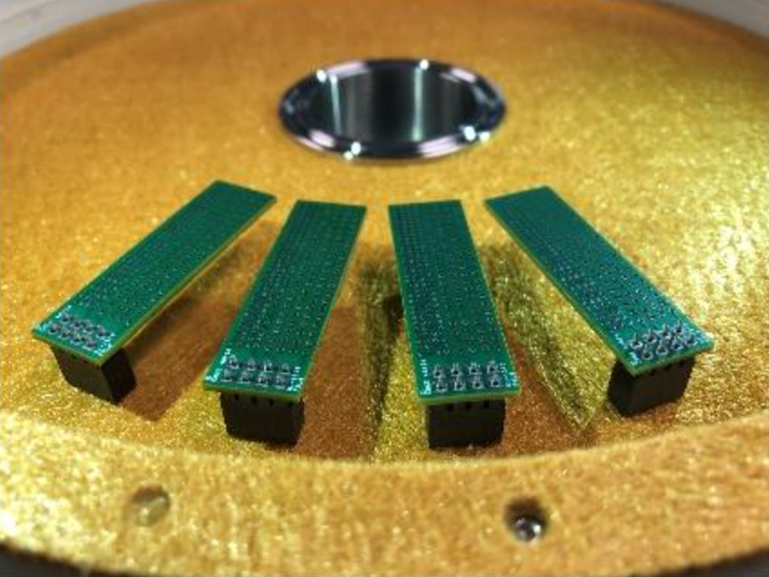
Fig. 2 D Coupons in OM tester
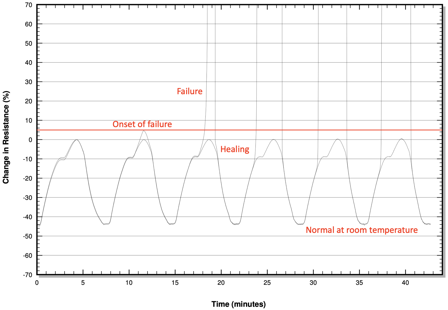
Given the rapid increase of tighter microvia densities and signal requirements in PCBs, reliability issues often appear after PCB fabrication, inspection and acceptance. Post fabrication microvia failures usually occur during the reflow stage of the assembly process and are often undetected at room temperature.
Coupon testing per existing IPC test methods can help alleviate latent microvia failures and prevent possible defect escapes. Thermal stress testing per IPC-TM-650, method 2.6.27 and thermal shock testing per IPC-TM-650, method 2.6.7.2 make use of performance-based test coupons utilizing resistance measurements.
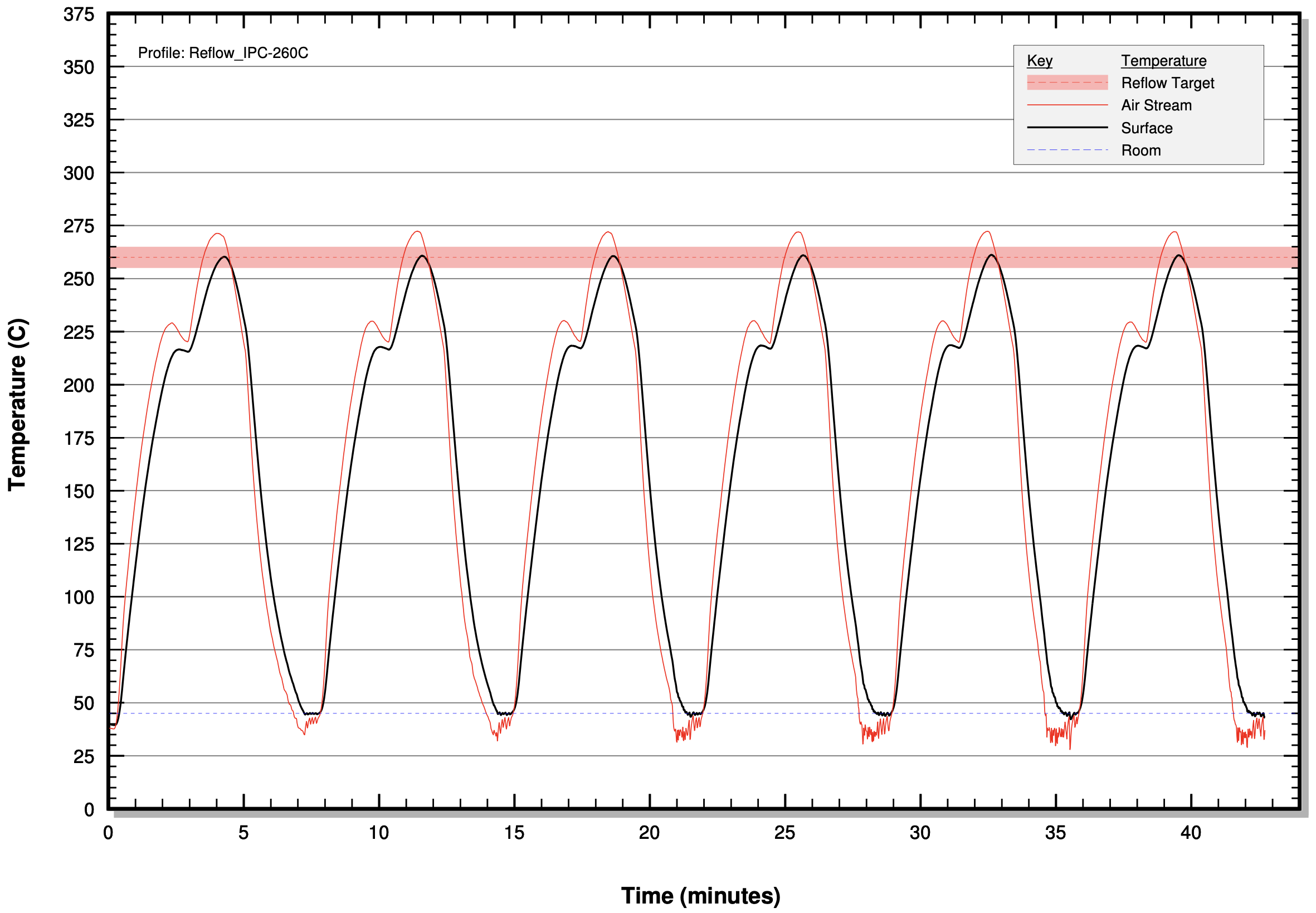
IPC-TM-650, method 2.6.27 thermal stress testing (Reflow Simulation) is used to simulate those effects that are the results of soldering thermal excursions. During this testing, coupons undergo multiple reflow cycles (6 minimum) with a peak temperature of 260°C (default reflow profile), 230°C (low temp profile) or 245°C (nominal reflow profile). Resistance of each coupon net is measured continuously and compared to each cycle. The maximum allowable percent change in resistance is 5% maximum. The percentage change in resistance is determined by using the first cycle’s peak temperature resistance as the reference.
After thermal stress testing, coupons are subjected to 100 thermal shocks per IPC-TM-650, method 2.6.7.2. The high temperature range is determined as the laminate Tg minus 10°C, the reflow peak temperature minus 25°C or 210°C. The low temperature range is typically -55°C. Resistance of each coupon net is measured continuously and compared to each cycle. Maximum allowable percent change is 5%. Note: A/B coupons typically undergo reflow simulation followed by microsectioning per IPC-TM-650, method 2.1.1. D coupons that have been evaluated by resistance change do not require microsectioning.
ORS has highly trained IPC staff who are prepared to assist with your testing needs.
ORS is pleased to offer performance-based reliability testing using the OM Thermal Stress System to meet IPC-TM-650 method 2.6.27 and 2.6.7.2 requirements.
Helpful Links:
IPC Gerber coupon generator:
https://ipcqmlcoupon.ipc.org/ipc-2221b-cg/abr-coupon/
IPC Test Methods: IPC TM-650 Test Methods Manual | IPC International, Inc.
IPC-TM-650:
- Thermal Stress, Convection Reflow Assembly per IPC-TM-650 method 2.6.27
- Thermal Shock, Thermal Cycle and Continuity per IPC-TM-650 method 2.6.7.2
- Microsectioning, Manual and Semi or Automatic per IPC-TM-650 method 2.1.1
- Dimensional Inspection using Microsection per IPC-TM-650 method 2.2.5
Mil-Prf-31032 Test Method:
- Convection air oven reflow soldering; low temperature or high temperature, Appendix F (Test condition D or F )
Mil-Prf-55110, 50884, and 31032/1 through /6:
- Thermal Stress, Convection Reflow Assembly per IPC-TM-650 method 2.6.27
Mil-Prf-31032/5 and /6:
- Thermal Shock, Thermal Cycle and Continuity per IPC-TM-650 method 2.6.7.2
Fig. 3a Reflow simulator graph
Fig. 3b Resistance change graph


