Destructive Physical Analysis (DPA) Testing of Magnetic Components
Magnetic components are characterized as passive devices that generate an internal magnetic field based on the magnitude and direction of electrical current. The magnetic field generated is a store of energy. Typical magnetic components are categorized as inductors, transformers, simple coils and ferrite chips based on their configuration. To meet circuit designs, reliability and environmental requirements, magnetic components are available in many different package designs. Requirements for military and aerospace application are addressed in military performance and test method specifications.
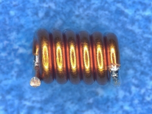
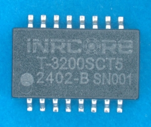
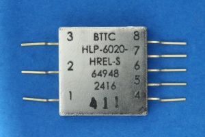
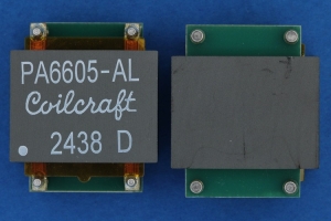
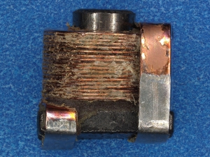
Representative images of various magnetic device design and packaging.
A wire wound in a single direction forms a coil creating a device that exhibits inductive reactance in alternating current circuits. This is referred to as impedance, it impedes changes to current flow. When used for this effect, a coil is referred to as an inductor. The magnitude of the inductance can be varied by adding a core material and number of windings. Voltage is dropped equally across each winding of wire forming an electric field. A transformer is formed by placing and additional wire/winding onto the core or onto a separate core isolating the coil windings, referred to as primary and secondary windings. Varying the number of windings will either increase or decrease voltage levels while stabilizing the circuit’s voltage level and inversely affecting the current. They have a high voltage regulation in which the output voltage varies significantly with changes in the input voltage. Typical applications of inductors and transformers influence their names:
- Common-mode choke
- Low-pass filter
- Toroid and choke
- Flyback
- Audio
- Isolation
- Power
- Pulse
Coils are typically used in conjunction with transformers or inductors. They can be used to transmit heat, electricity or sound. Coils made of wire (typically copper) that winds around a toroidal core include:
- Fixed Radio Frequency
- Variable Radio Frequency
Contact us for information about magnetic components testing
Ferrite Chips are noise-suppression components. The chip is made of coil patterns (electrodes) that are formed between the ferrite. The construction of a ferrite chip is the same as a multilayer type of chip inductor with the difference being the ferrite material.
Non-destructive testing includes external visual examination, prohibited material inspection, and X-Radiography. Hermeticity and terminal strength testing is also applicable depending on the package. Of these tests, X-Ray provides the most meaningful data as the internal construction can be inspected well. It is very common for extraneous material such as solder balls to become entrapped between wires or embedded within the packaging material. These small extraneous materials are quite difficult to locate during the destructive phases of testing, thus X-Ray can provide useful data without destroying the component itself. X-Ray is performed in accordance with Mil-Std-981.


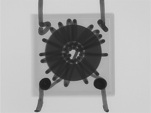
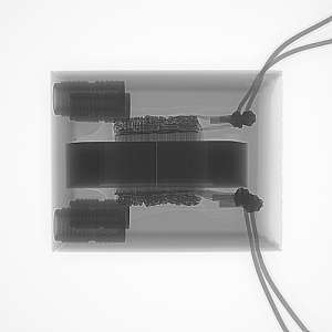
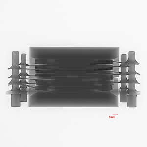
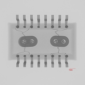
Non-Destructive X-ray radiography of Transformers
Destructive testing consists of disassembly/decapsulation and cross-section. Given the wide range of packaging materials available; disassembly can sometimes be arduous. The disassembly process allows for inspection of the internal wire connections as well as the core. Cross-section inspection is performed as a means of inspecting the internal wire connections. It can also be performed to confirm X-Ray findings.
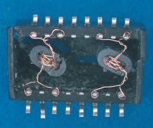
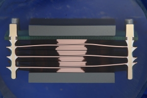
Destructive Test Images
Test Specifications:
Destructive physical analysis of Magnetic components are coveredby test methods in the following Military Standards:
- Mil-Std-1580 revision C, Requirement 15
- Mil-Std-981C – Design, Manufacturing and Quality Standards for Custom Electromagnetic devices for Space Applications
Associated DLA performance specifications:
- Mil-Prf-27 – General Specification for transformers and inductors (audio, power, and high-power pulse)
- Mil-Prf-15305 – General Specification for coils, fixed and variable, radio frequency
- Mil-Prf-21038 – General Specification for transformers, pulse, low power
- Mil-Prf-39010 – General Specification for coil, radio frequency, fixed, molded
- Mil-Prf-83446 – General Specification for coils, radio frequency chip, fixed or variable