Mechanical Shock Testing
Mechanical shock testing looks at the effects of suddenly applied forces or abrupt changes in motion, which may disturb operating characteristics or cause damage, particularly if the shock vibrations are repetitive.
A mechanical shock test can determine the suitability of a device for use in electronic equipment that is subjected to moderately severe shocks from rough handling, transportation or field operation. Mechanical shock testing utilizes shock and drop testing and is considered destructive.
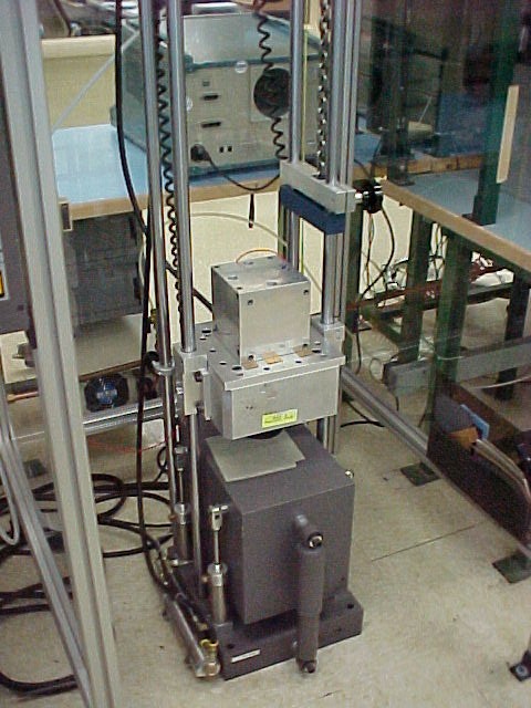
The Shock Apparatus is a commercial piece of mechanical shock equipment designed to provide a Half-Sine Shock Pulse. Typically, the device is subjected to 5 shock pulses of the peak (g) level specified in the selected test condition and for the pulse duration specified in each of the orientations X1, X2, Y1, Y2, Z1 and Z2. For devices with internal elements mounted with the major plane perpendicular to the Y-axis, the Y1 orientation shall be defined as the one in which the element tends to be removed from its mount. Typical conditions are 500g for 1.0 ms and/or 1500g for 0.5 ms.
- Test Specifications / Standards
- JESD22-B104
- AEC-Q100
- AEC-Q101
- AEC-Q200
- GR-468-CORE
- MIL-STD-202 Method 213
- MIL-STD-750 Method 2056
- MIL-STD-883 Method 2002
Tooling is generally required to attach a component to the Shock Apparatus. The simplest and least expensive is to add holes to our existing adapter plates if the component has screw attachment holes. If the component has no such attachment means, special fixtures must be designed and fabricated. These unique fixtures are then attached to the mounting block. This unique design allows for the shock and vibration testing of all six axes.
Tooling allows the accelerometer to be mounted close to the centerline of the component being shocked. As standard practice, the new tooling will run dry (without test components) to calibrate the machine. Calibration is performed in all orientations before the product is run.


