Destructive Physical Analysis (DPA) Testing for Relays
There are two common categories of relays that are subjected to DPA testing: electromechanical relays (EMRs) and solid-state relays (SSRs). EMRs have contacts that are open or closed using magnetic force. EMRs employ at least two circuits; the energizing (input) circuit and the contact (output) circuit(s). The energizing circuit consists of a coil, similar to an inductor, that produces a magnetic field when current flows through it that moves an armature. The armature pivots and usually has arms with glass beads that move a center common contact known as a moveable contact. The moveable contact functions to select the position of the contacts – open or close.
Pole is the number of completely isolated circuits that can pass through a switch. Current can be carried through only one circuit at a time for single-pole contact while double-pole contact can carry current through two isolated circuits simultaneously. Throw is the number of closed contact positions per pole that are available on a switch. A switch with a single throw contact can control one circuit, whereas a double-throw controls two.
SSRs differ from electromechanical relays as they do not employ mechanical metal contacts and the switching occurs electronically. They also have an input control circuit side and an output circuit. The input circuit performs the same function as the coil used in electromechanical relays, however, the circuit is activated or deactivated when voltage is applied. The voltage needs to be higher than the pickup voltage to activate the circuit. When the voltage applied is less than the required dropout voltage, the circuit is deactivated. The control circuit determines when the output circuit is energized or de-energized. The output circuit performs the same function as the mechanical contacts of electromechanical relays by switching on the load. Typically, SSRs have only one output contact. DPA of SSRs are performed as integrated circuits.
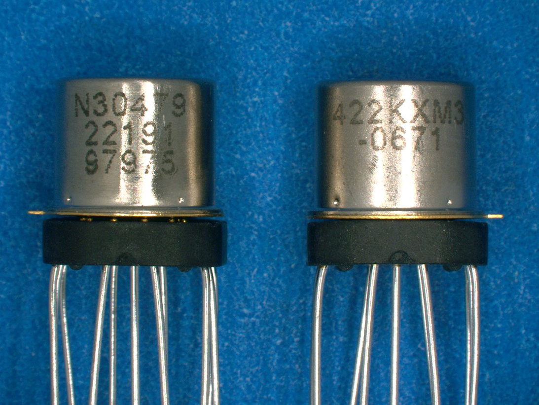
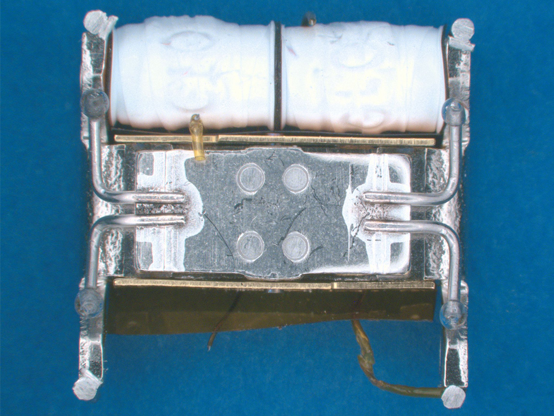
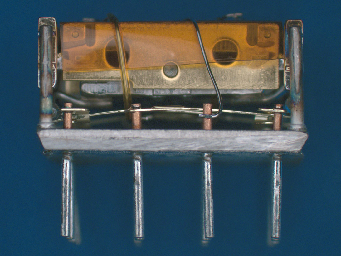
Electromechanical Relay Example 1
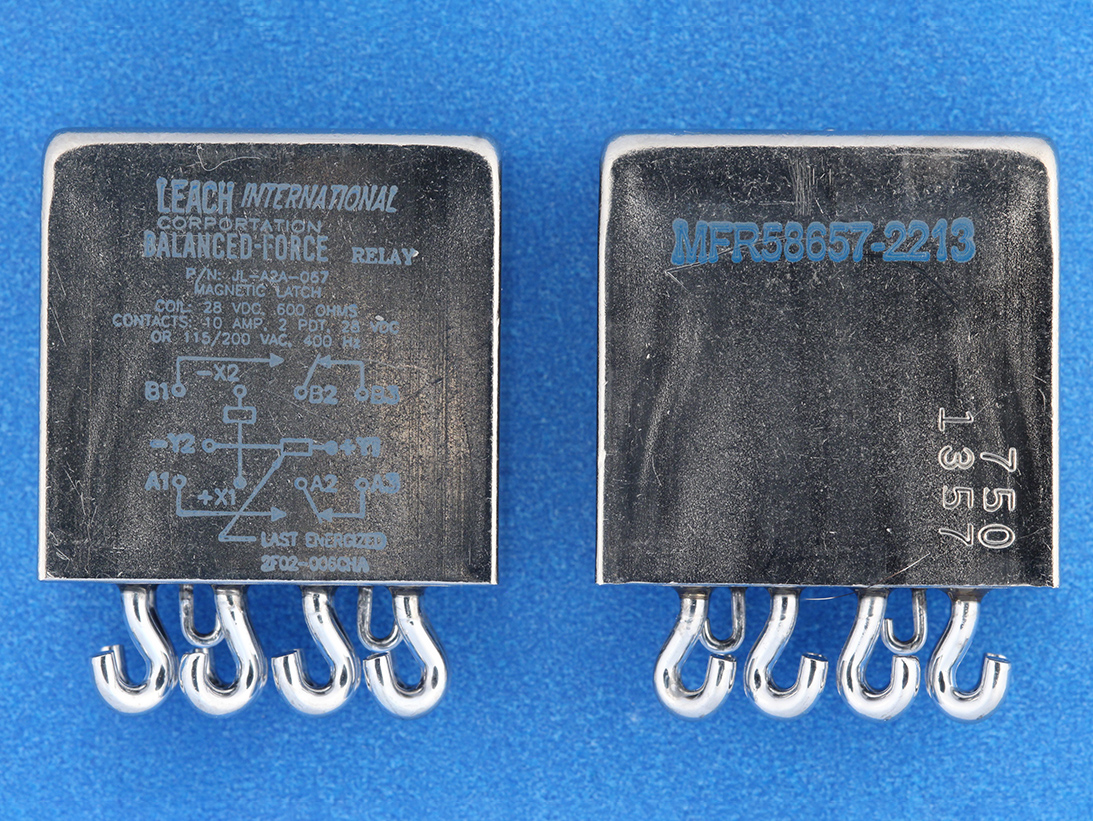
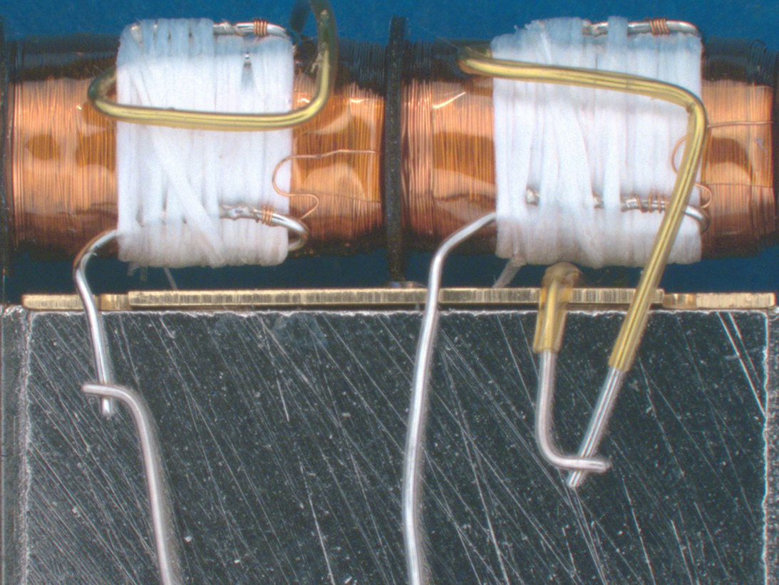
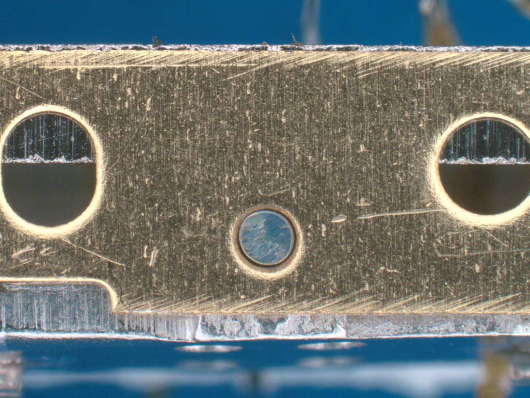
Electromechanical Relay Example 2
ORS Offers FAST Reliable Relay DPA
Typical EMR packages include hermetically sealed metal with lid welds, glass seals and plastic encapsulation. These are prevalent in Aerospace, Military and Automotive systems and are subject to the following qualification requirements: MIL-PRF-6106, 39016, DPA MIL-STD-1580 Req. 17 and MIL-STD-202.
Destructive Physical Analysis
ORS has over 40 years of experience performing comprehensive testing designed to identify anomalies that can lead to field failure.
DPA testing of relays includes non-destructive and destructive testing. Non-destructive testing consists of external visual examination, hermeticity testing, X-radiography and prohibited material inspection. Hermeticity testing is crucial as most relays employ header glass seals. IVA/RGA testing is performed on one device for reference purposes only. Destructive testing consists of mechanical removal of the enclosure (delid). Due to the many packaging variations for relays, different techniques are employed to carefully remove the enclosure. Great care must be taken during delid as internal examination of internal components is critical. After internal examination is complete, the coil assembly frame is pull tested to inspect the robustness of the spot weld.
Contact us for information about relay testing
Non-Destructive Test Methods
An important part of a Relay DPA are the applicable initial non-destructive test methods – external visual inspection with physical dimensions/configuration compliance, X-ray Radiography, electrical testing, Hermeticity testing, which may include particle induced noise detection (PIND) and prohibited material analysis (PMA).
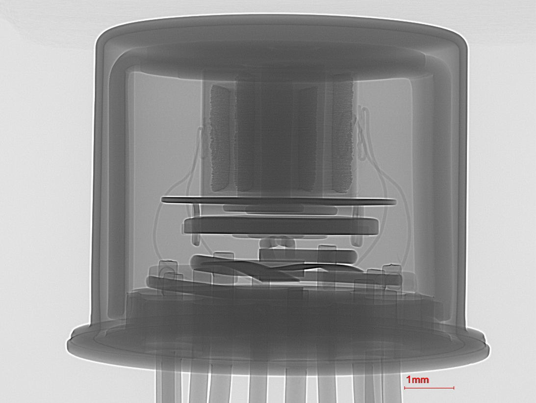
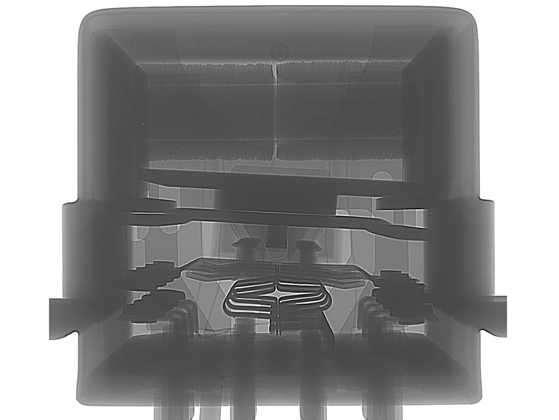
Side X-ray view
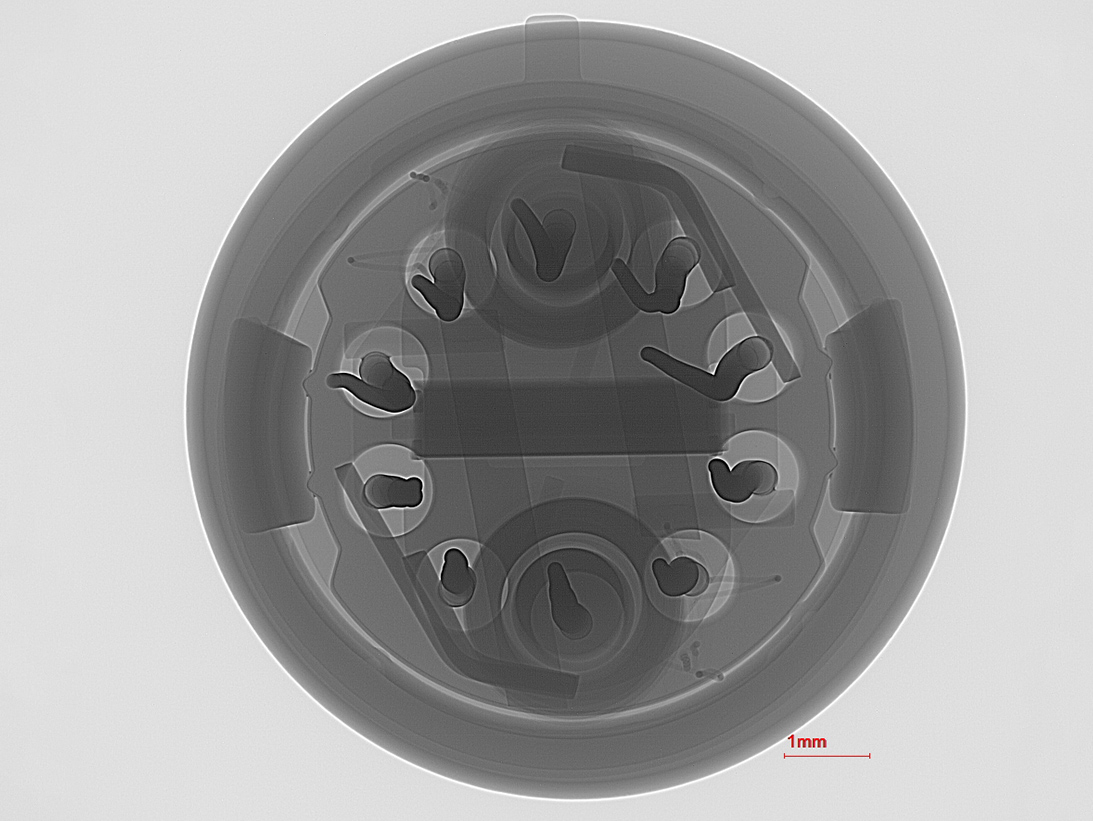
Z-axis X-ray view of Relay
Y-axis view
Images of Destructive Analysis Methods of Relay Testing
A complete DPA of relay could include destructive test methods such as IGA – internal gas analysis or internal visual inspection achieved by de-lidding/de-encapsulation. Mil-STD-1580 includes suggested opening methods. Relays with die also require die shear testing and interconnect wires in accordance with MIL-STD-883. SEM with energy dispersive X-ray (EDS) analysis may be utilized for internal prohibitive materials analysis testing.
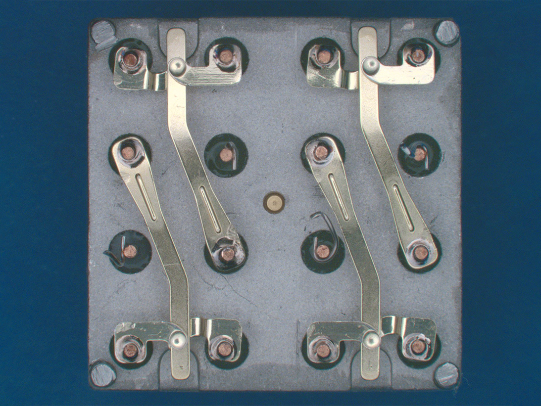
Internal visual inspection of contact alignment
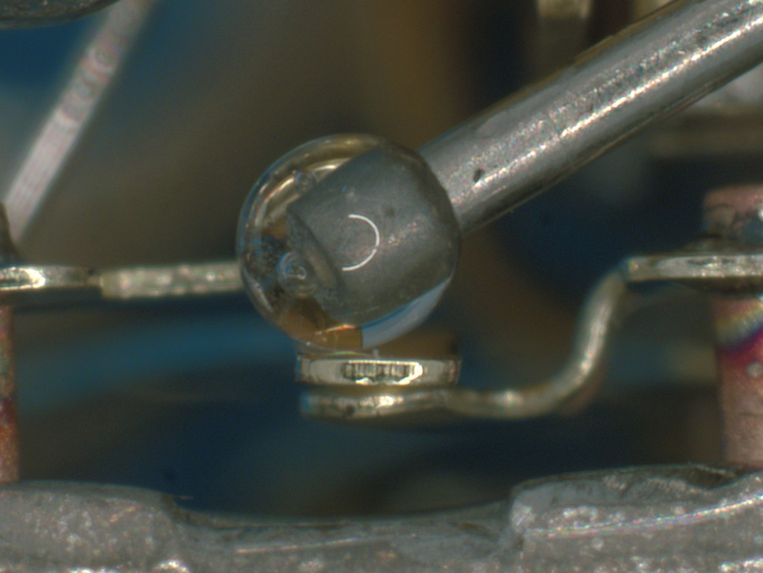
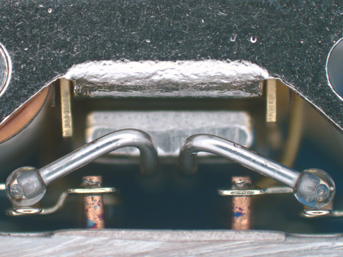
View of actuator bead
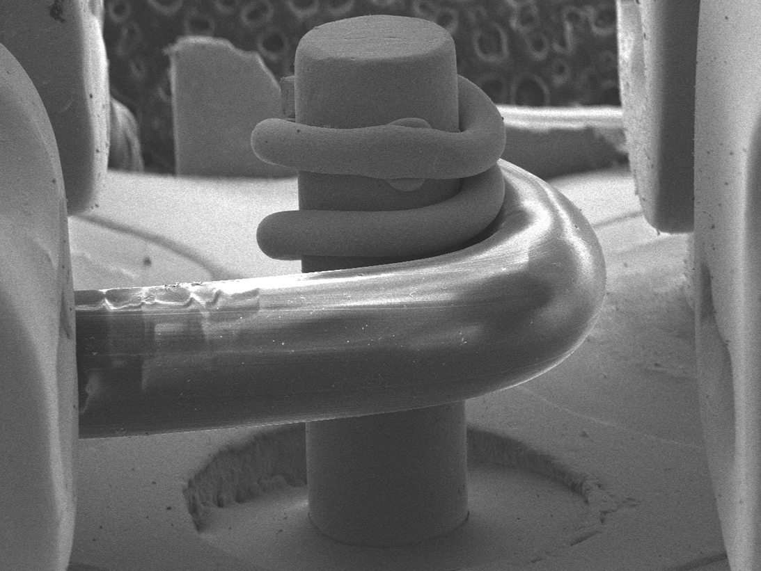
SEM image of internal post
Internal view of dual coil
Internal side view
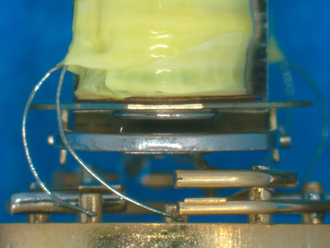
Coils connections
Armature pivot point
Stationary contacts
Internal lead weld to post
Armature and actuators
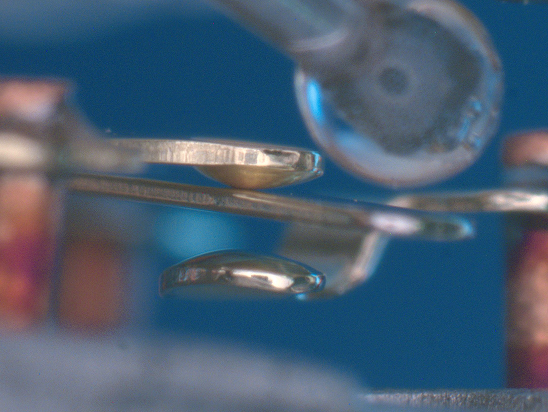
Bead to moveable contact
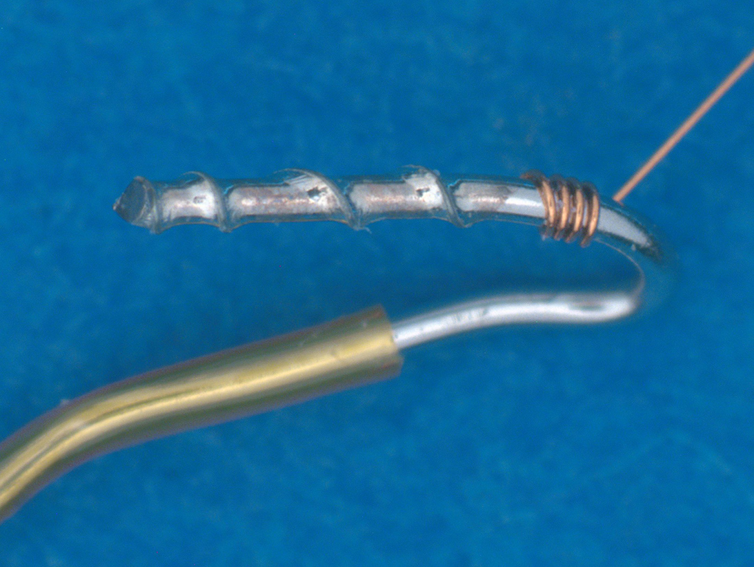
Coil wire attachment
Failure Modes of Relays That Can Be Revealed by DPA:
Failure modes of Relays will depend on construction and by application.
The two most common failure modes are mechanical wear and contamination. Degradation of contacts can occur over time due to high-sustained current or high voltage spikes. Additionally, pitting or contamination of a contact can further degrade its life. Relays can also fail due to poor contact alignment and open coils. Early life failure is likely caused by contamination; non-metallic and metallic. Non-metallic contamination may be present due to the various chemicals that are present in the manufacturing process; such as soldering fluxes, cleaning agents and adhesives. Non-metallic or gaseous contamination can create open circuits if it periodically deposits itself on contacts. This can result in:
- Loss of Hermeticity/lid and glass seals
- Coil wire breaks
- Pure tin at external and internal surfaces
- Undisclosed product changes
Applicable Industries:
- Space
- Aerospace
- Military Terrestrial
- Automotive/Commercial
- Mainframe Computers
Military Standards:
- MIL-PRF-6106, 39016, 83536
- MIL-STD-1580/Req 17
- MIL-STD-202 various Methods
Summary of Relay Testing Methods
MIL-STD-1580 Requirement 17
- External Visual 10x – 30X
- Header glass seals
- Finish and plating verification
- Terminal studs and mounting
- Radiographic examination for internal construction
- Hermeticity – MIL-PRF-6106
- Internal Gas Analysis
- Internal Visual Examination 20X min.
- Contamination, alignment
- Contacts and terminals
- Armature and pole piece
- Coil security and clearance
- Prohibited Materials Analysis Req. 9

