Destructive Physical Analysis (DPA) Testing of Fuses
Fuses are very simple devices, but provide great circuit protection!
A fuse serves a basic function, but is intrinsically required to be highly reliability. Its basic function is to serve as safety protection, preventing unexpected long-duration excess current events caused by other component failures or improper use such as a short circuit condition in a circuit. When an overcurrent condition occurs, the fuse element melts open or “blows,” which interrupts current flow to the protected circuit, preventing over-heating and electrical shock.
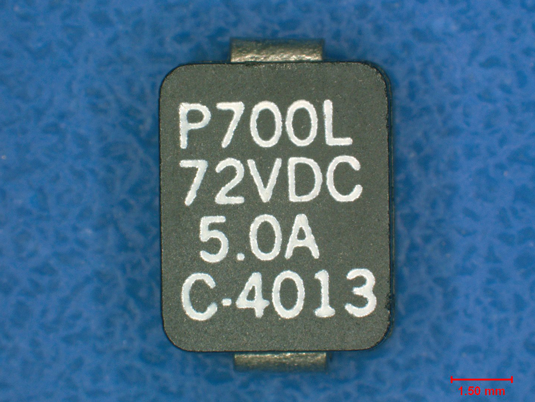
SMT
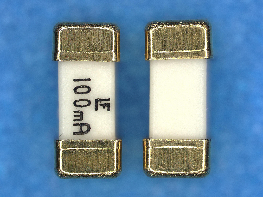
SMT Ceramic
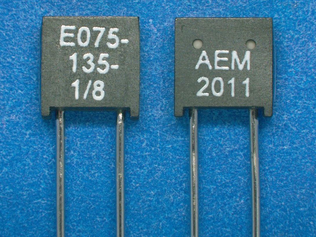
Through-hole
High-Reliability Fuses
To ensure high-reliability performance, Fuses used in critical applications are designed and constructed to specified military performance specifications such as MIL-PRF-15160 and 23419. The military performance specifications provide requirements for qualification of Fuses used in micro-electronic circuits that ensure high-reliability performance. Qualification testing includes electrical tests and physical test methods from MIL-STD-202, such as vibration, shock, salt-spray and moisture-resistance testing.
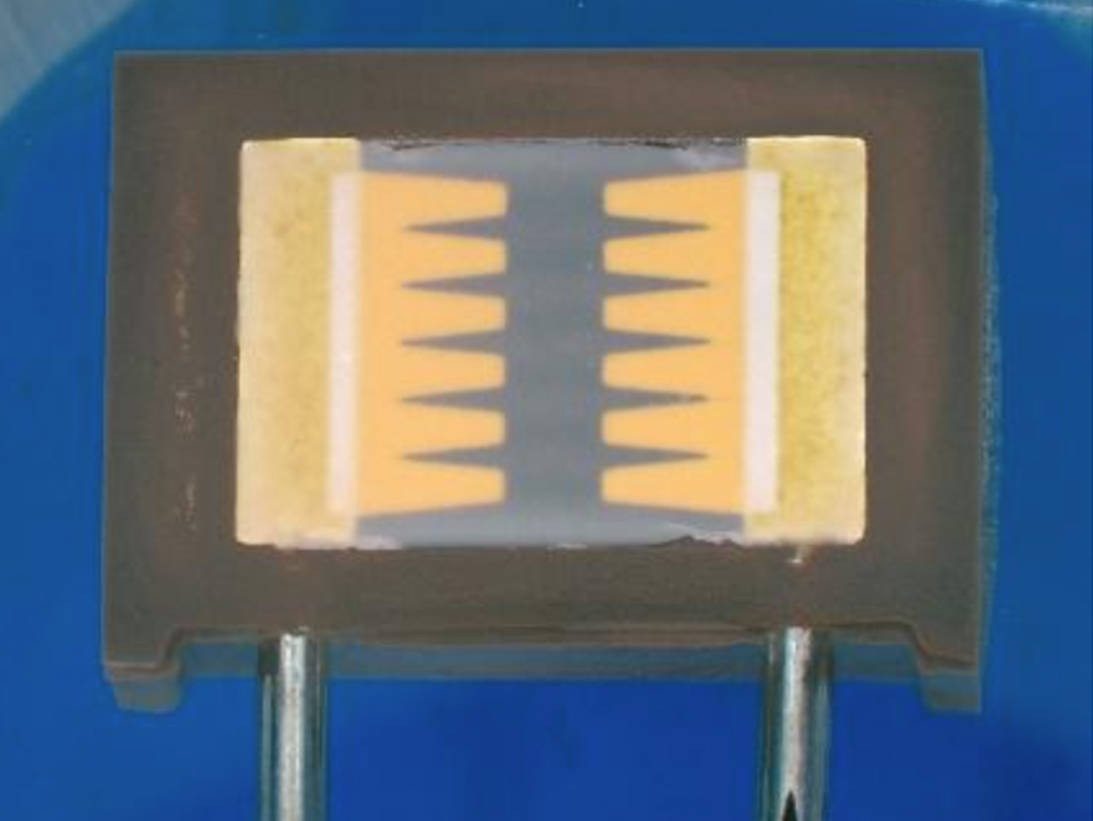
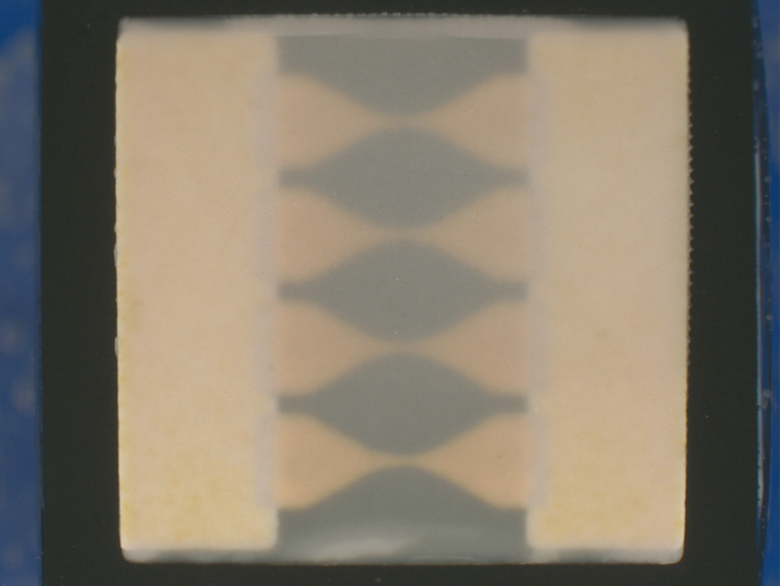
Typical designs include a conductive thick-film technology using precious metal(s), applied to a ceramic substrate, that is flattened and cut into a desired shape creating the fuse element. A common fuse element may be a round or ribbon wire with solder attachment construction. The fuse element may also be covered with an arc-suppressant to prevent damage to other components when blown. The fuse element is then placed into a hermetic housing with ceramic or glass attributes. Each fuse element is designed to carry a limited electrical current. When current flows through the fusing material it heats. When the current flow is above the designed limit, this causes it to melt or fuse-open, interrupting current flow protecting other circuit devices.
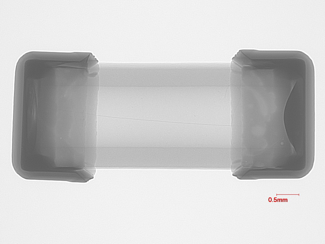
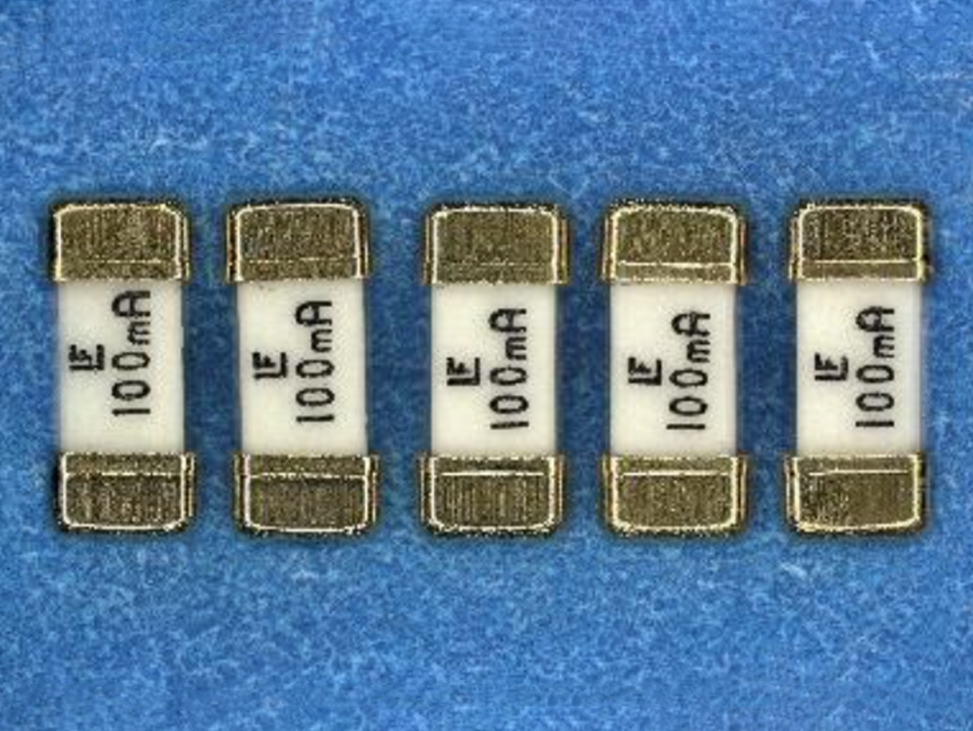
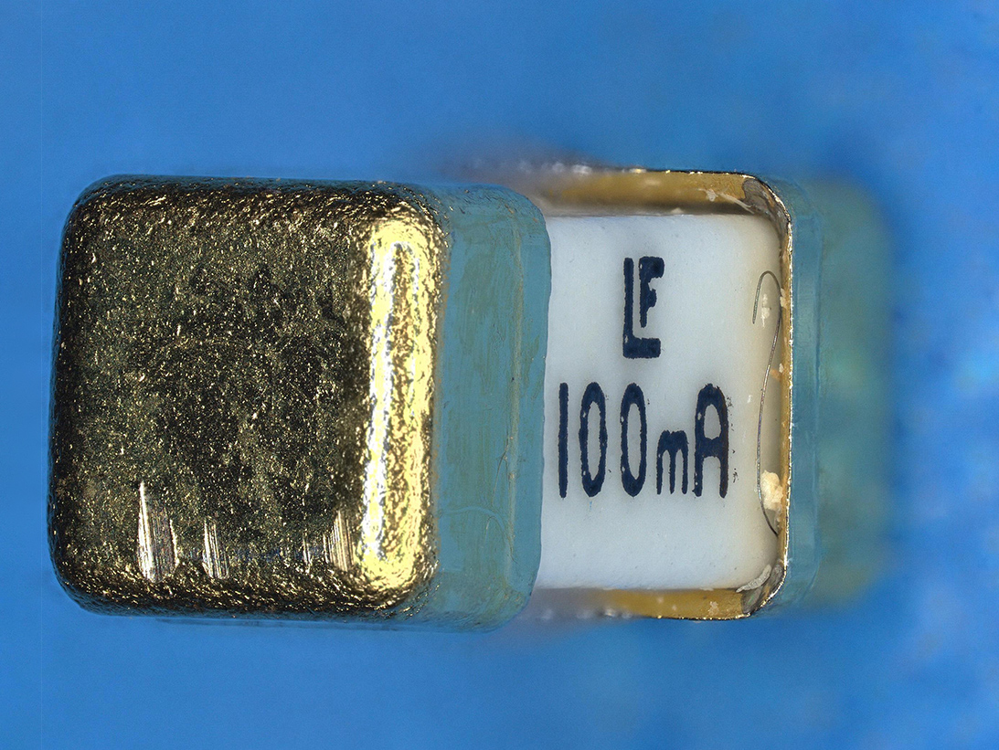
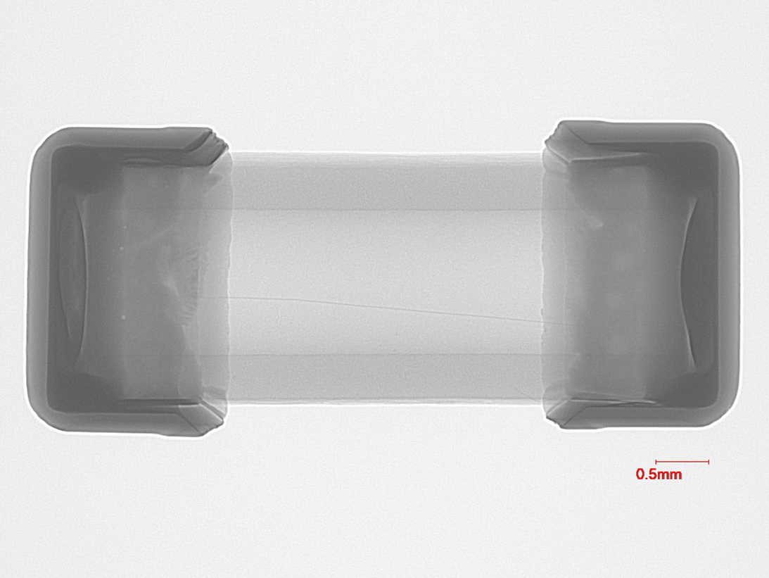
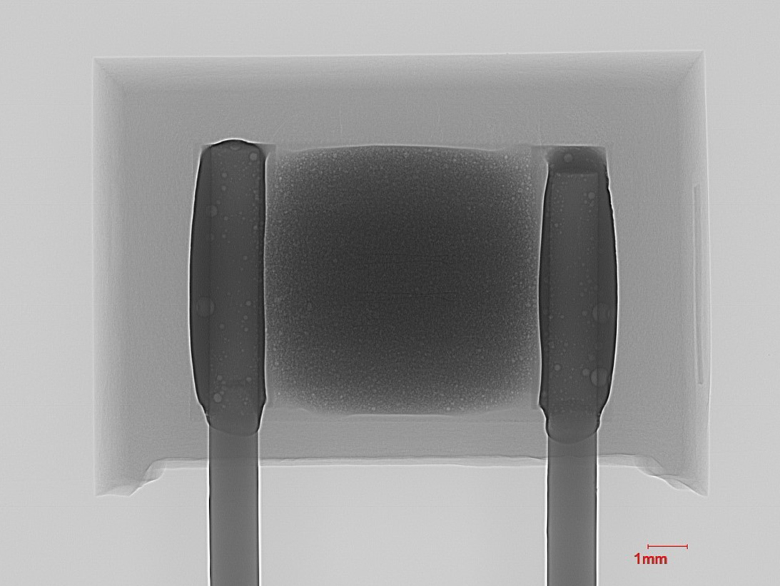
Fuse device package example 1
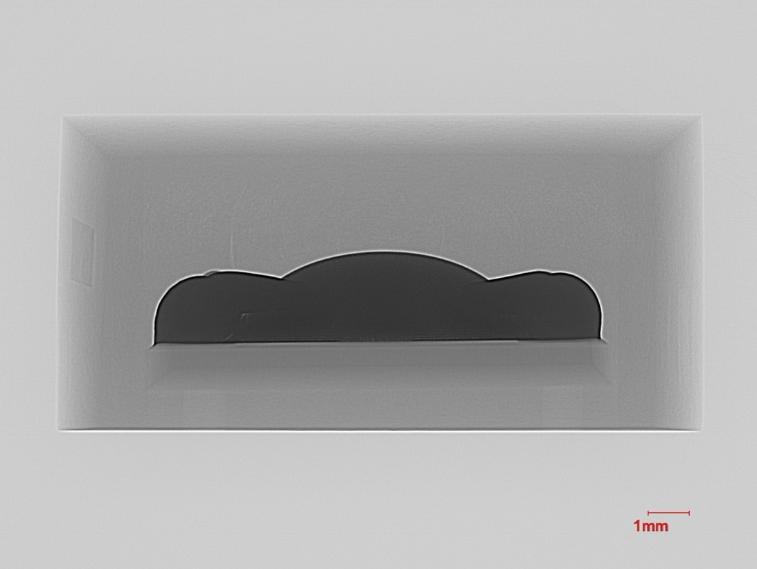
X-Ray image of a surface mount fuse. The wire inside is the fuse element, which is attached to the terminations.
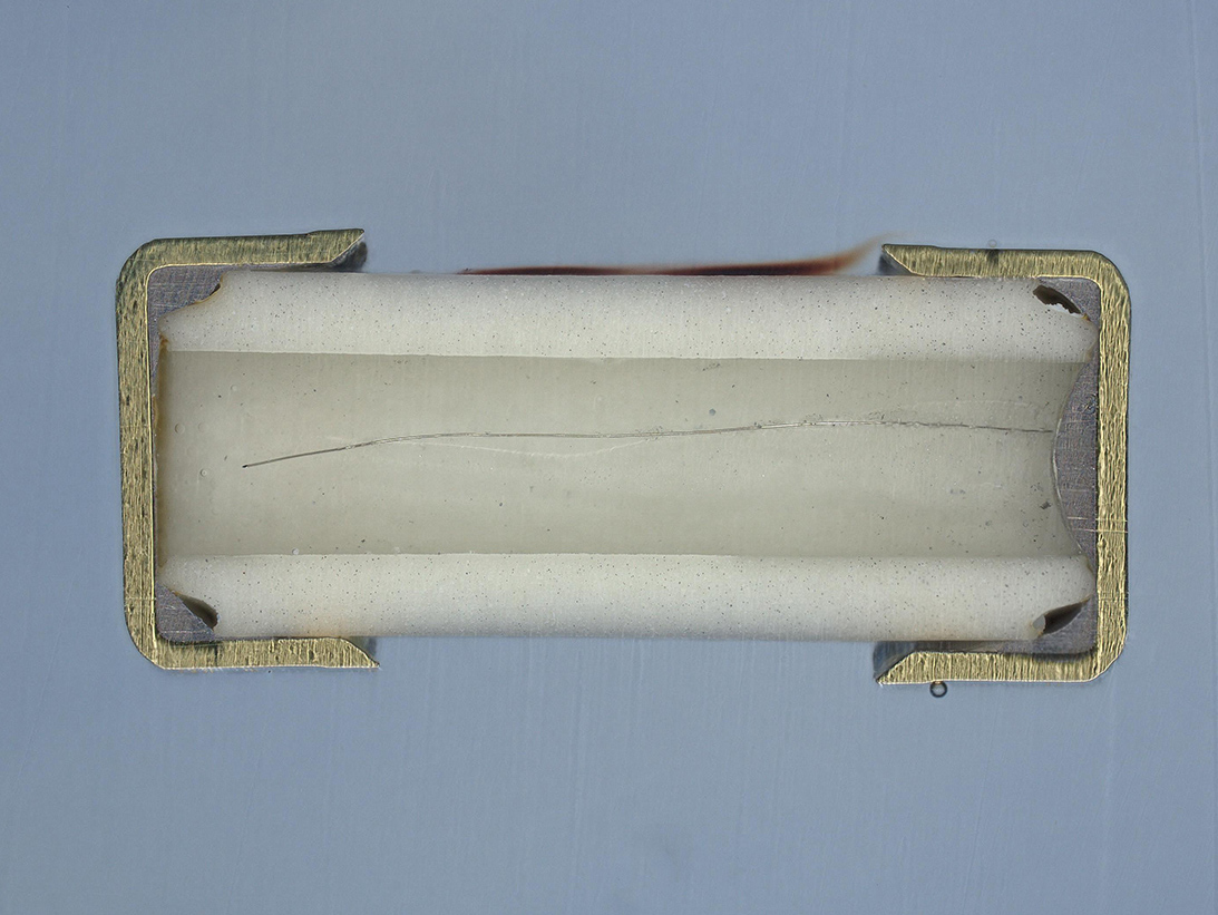
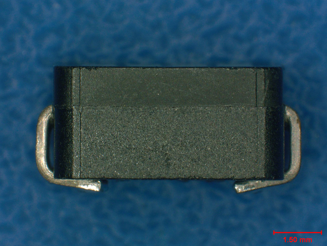
Fuse device package example 2
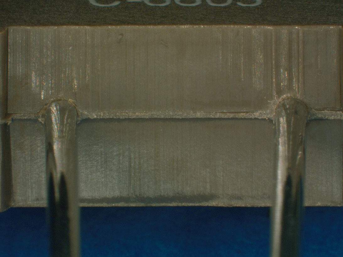
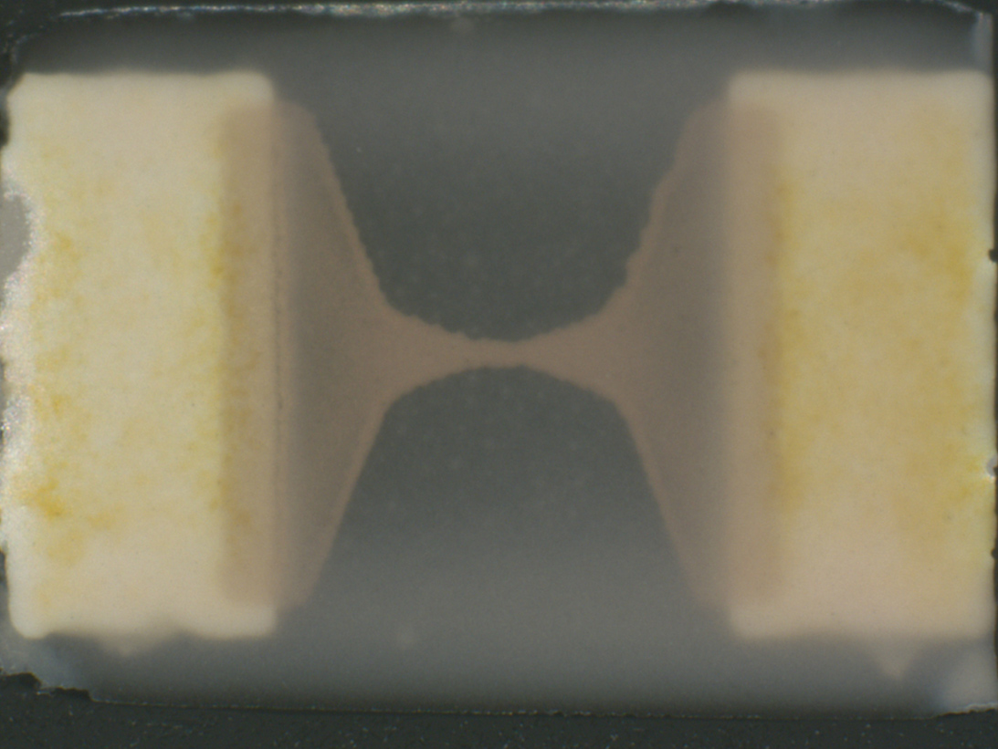
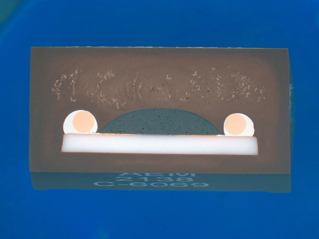
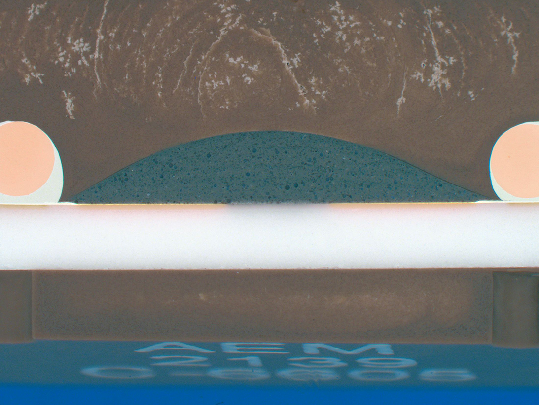
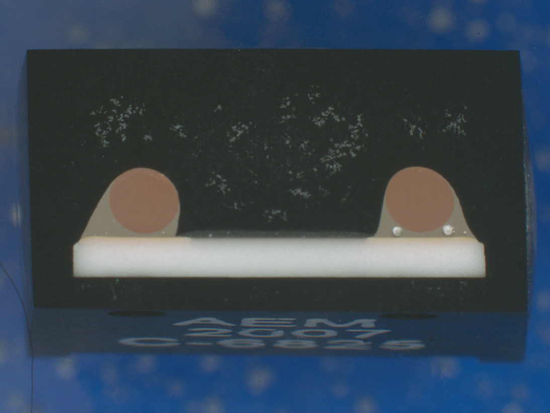
Optical image of cross-section surface mount fuse depicting wire and attachment to termination.
ORS Offers FAST Reliable Fuse DPA
Fuses are a fundamental component critical to the function of nearly all electronic circuits. Due to their wide-ranging applications, packaging of discrete Fuses vary to meet environmental, power and application requirements.
Fuse device construction variations require specific test methods in DPA testing based on the Mil-PRF designs and Aerospace requirements.
ORS has over 40 years of experience performing comprehensive testing designed to identify anomalies that can lead to field failure.
ORS DPA techniques for Fuses have effectively revealed improper package markings, Hermetic failures, fuse defects, and voiding in arc-suppressant and lead solder joints.
Failure Modes of Fuses that can be revealed by DPA:
Failure modes of Fuses will depend and vary on construction and by application.
Fuses can degrade over time due to aging or corrosion, which can lead to failure. Additional failure modes are:
- Spurious opening: The fuse element opens and causes an open circuit when it shouldn’t.
- Fatigue: Weakening of the fuse element caused by repetitive or loading cycles, which cause thermal stress and damage.
- Heat Damage: Excessive heat can degrade the fuse element and can lead to intermittent issues.
- Internal Corrosion: Over time, the internal metal surfaces of a fuse can corrode due to moisture or other environmental factors, which lead to increased resistance. This condition can cause a fuse to fail as it may not conduct electricity properly without blowing.
DPA Test Specification:
Fuses are covered within MIL-Std-1580 Revision C, Requirement 23.
Contact us for information about fuse testing
Non-Destructive Test Methods
An important part of a Fuse DPA are the applicable non-destructive test methods that need to be done first. Non-destructive testing of fuses includes external visual examination with physical dimensions/configuration compliance, prohibited material analysis and radiographic inspection. The fuse element can be effectively inspected utilizing radiography; however, this is dependent on the fuse element material density and arc-suppressant material.
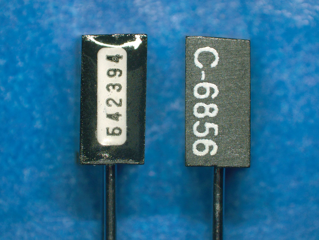
Device markings
Termination inspection
X-ray axial view
Device markings
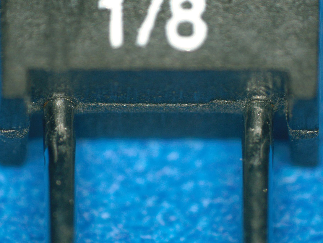
Lead egress
X-ray view (arc suppressor)
Side view
Lead egress seal
X-ray view
Destructive Analysis Methods of Fuse Testing
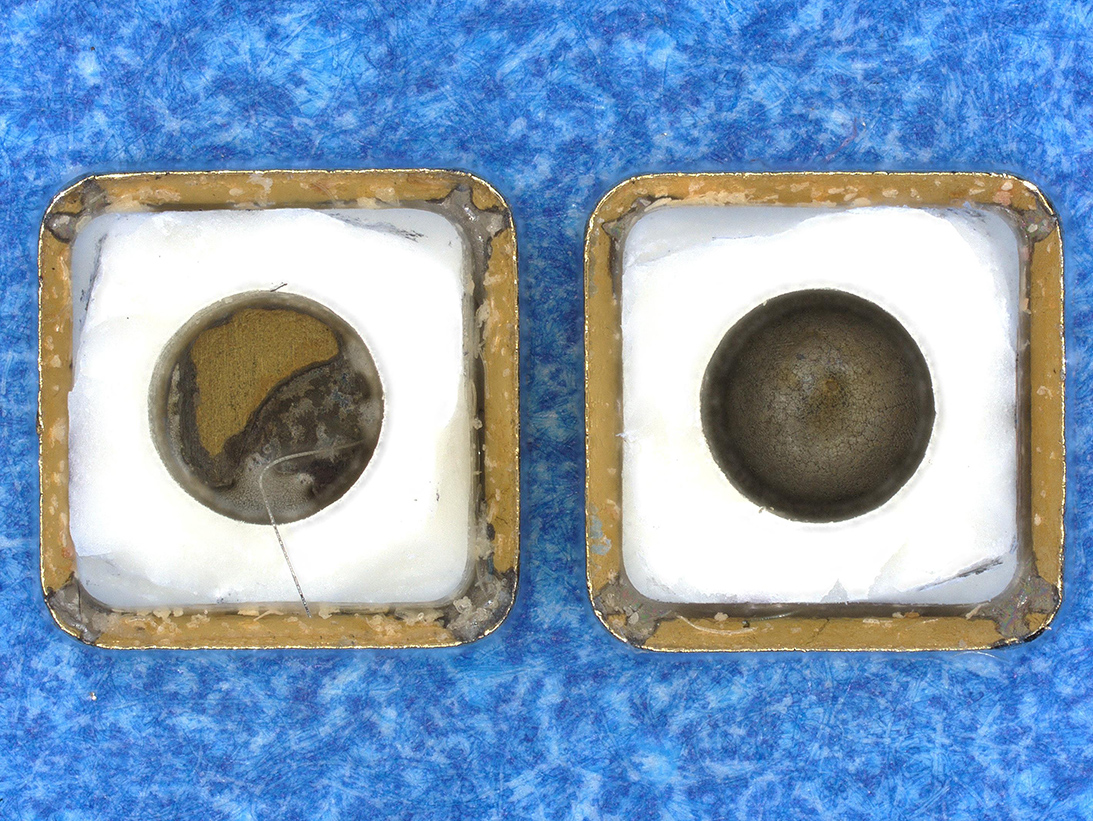
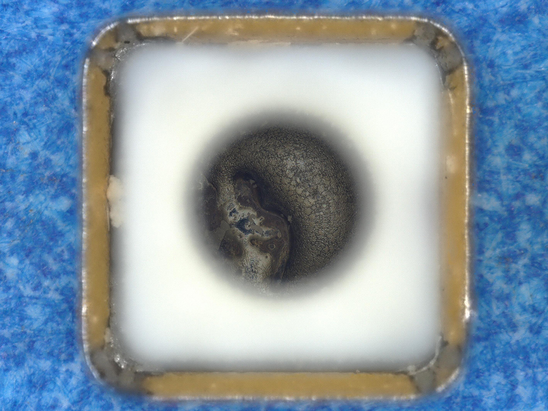
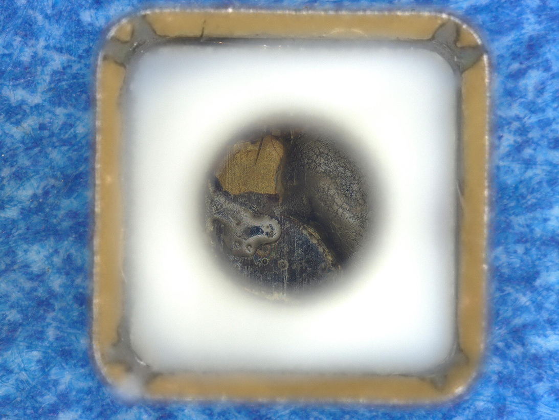
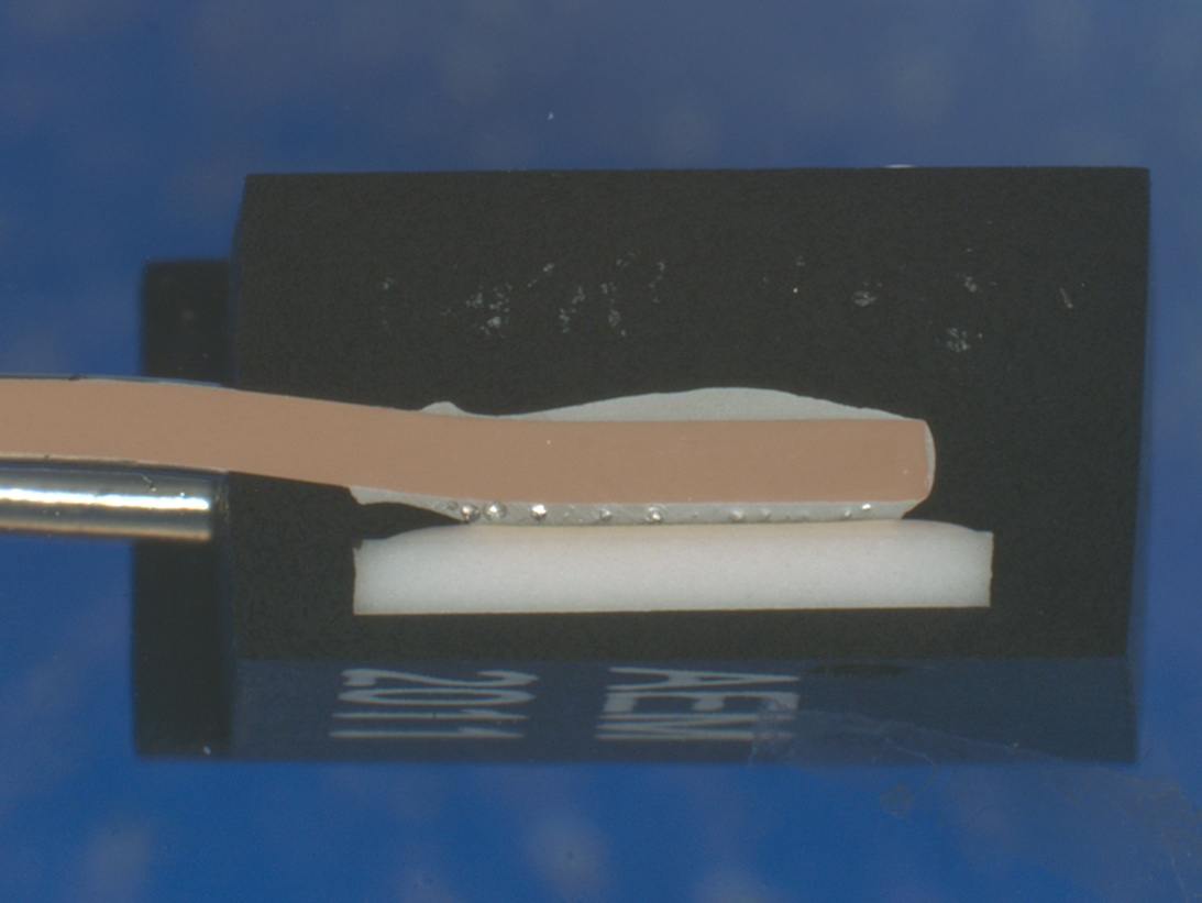
Destructive testing consists of disassembly and/or cross-sectioning. Both methods allow for internal inspection of the fuse element as well as interior surface inspection.
Disassembly Views
Optical image cross-sectioned fuse element
Optical image cross-sectioned fuse element
Optical image cross-sectioned fuse element
Disassembled SMD fuse
Internal area of the fuse after disassembly
Opposing internal area after disassembly
Cross-Sectional Views
Porosity in encapsulant
Suppressant
Wire attachment
Porosity in encapsulant
Lead attachment
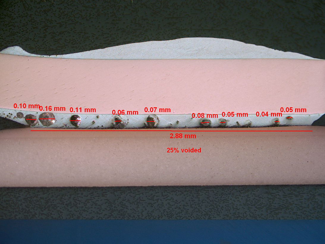
Voiding in lead solder
Associated DLA Performance Specifications:
- MIL-PRF-15160 – General Specification for Fuses, Instrument, Power and Telephone
- MIL-PRF-23419 – General Specification for Fuse, Cartridge, Instrument Type
Applicable Industries:
- Space
- Aerospace
- Military Terrestrial
- Automotive/Commercial
- Mainframe Computers
Summary of Fuse Testing Methods
MIL-STD-1580 Requirement 23
- External Visual
- Defects
- Markings
- Workmanship
- X-ray Radiography
- Voiding
- Internal construction
- Internal Visual Inspection Methods
- Disassembly
- Cross-sectional

