Destructive Physical Analysis (DPA) Testing for PEMS
Plastic encapsulated microcircuits (PEMs) offer leading-edge technologies, the advantages of lighter weight construction, lower costs, flexibility and easier integration into multichip modules and hybrids than traditional hermetic packages. ORS provides special expertise in identifying anomalies in PEMs that can lead to field failure.
Viable applications for plastic devices in high-reliability systems have increased thanks to significant changes to manufacturing process monitoring, highly-modified epoxy mold compound resins, and advances in flame retardants in conjunction with inorganic particle fillers of various shapes and sizes.
The use of plastic encapsulated microcircuits, transistors and diodes (PED) has become prevalent in aerospace, military and automotive systems. These uses are subject to strict qualification standards and DPA mil-spec testing requirements.
ORS offers fast and reliable PEM/PED DPA
Screening and monitoring of plastic encapsulated devices is crucial to ensure that the materials, design, construction and workmanship that go into the manufacturing process are consistent with military and aerospace standards.
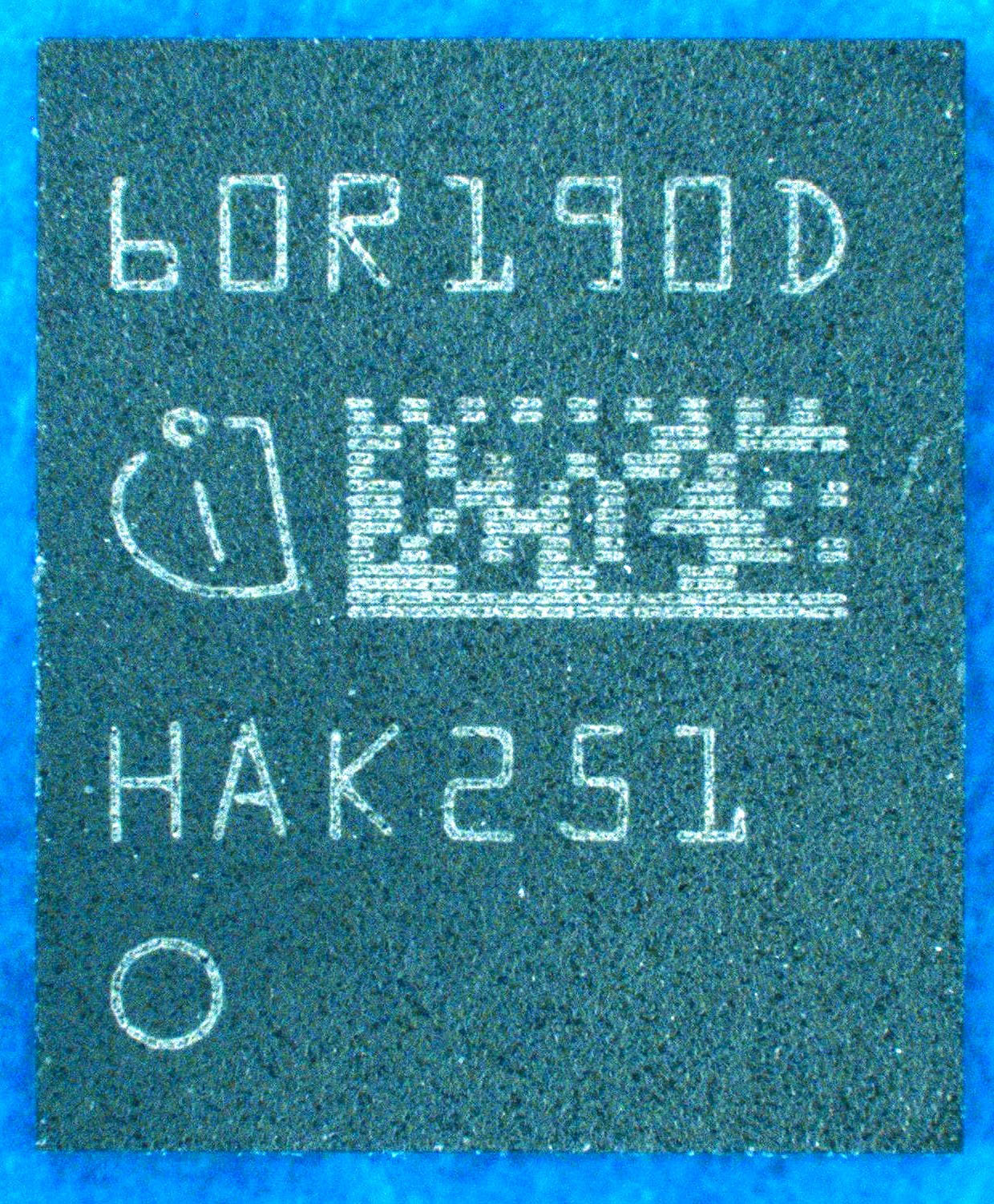
TSON
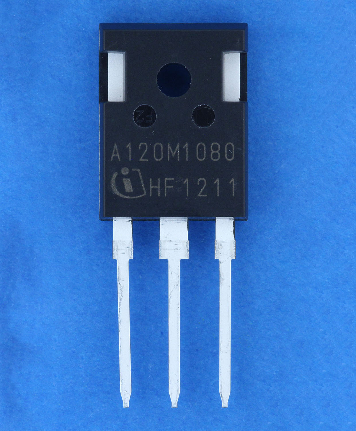
TO-247
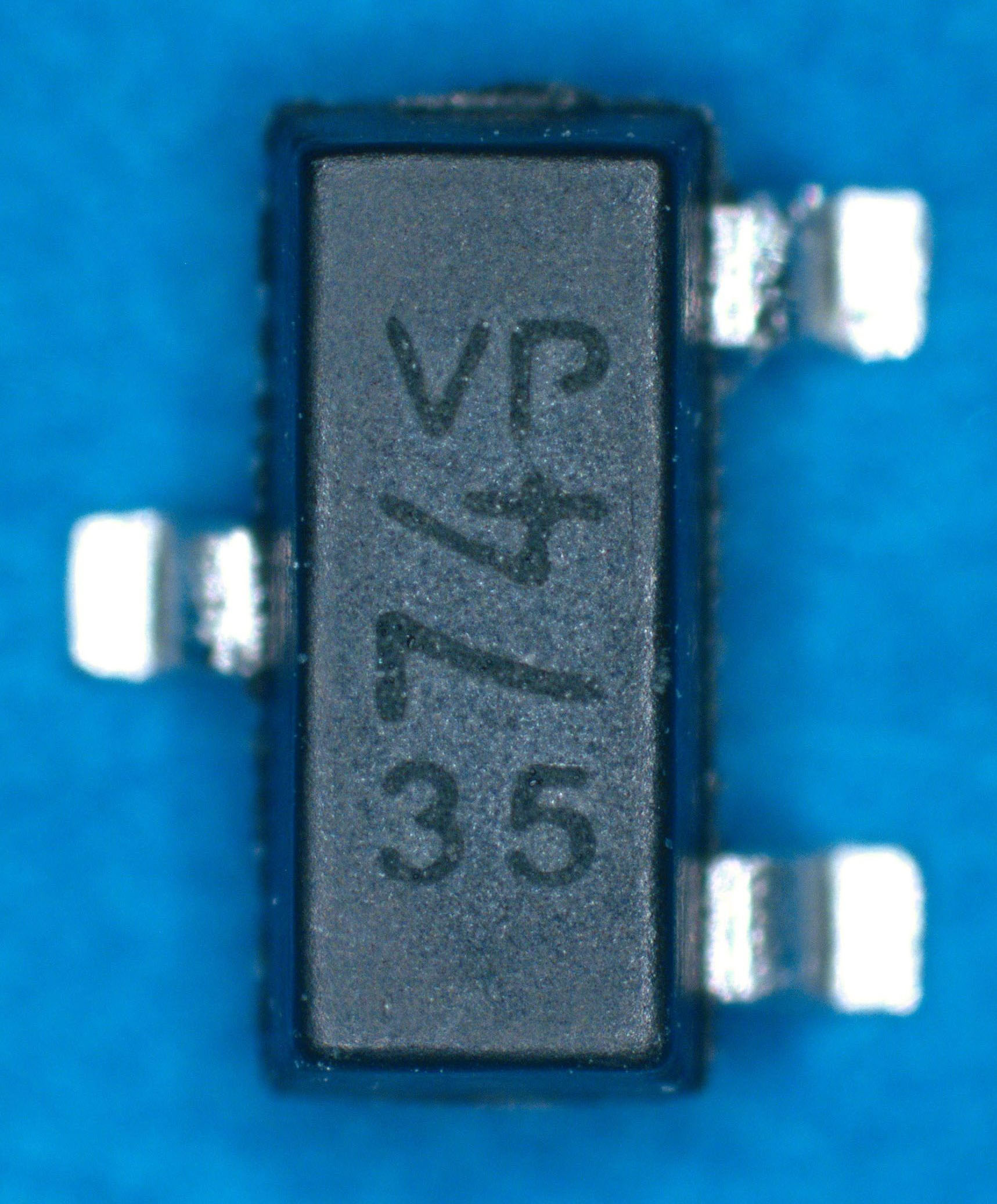
SOT-23
Destructive Physical Analysis
With over 40 years of experience performing comprehensive PEMs testing, ORS provides exceptional expertise in identifying anomalies that can lead to field failure.
ORS employs de-encapsulation techniques for testing PEMs that we have developed in house.* Proper EMC removal is a crucial step for effective internal visual inspection of die surfaces, wire bond formations, pull strength and bond shear testing. It’s also essential for subsequent dye de-processing that’s needed for the evaluation of metal step coverage.
ORS DPA techniques include cross-sectional analysis with dye penetrant to assess EMC adhesion along with testing for surface breaks and moisture sensitivity. We use multiple cross-sectional planes in the examination of critical features such as:
- Bond wire exit
- Evidence of wire thinning
- Assessment of intermetallic growth in bi-metallic systems
- Effective secondary bonding/placement
- Die attachment coverage
- Fillet formation, including silver flake dispersion
We are able to elementally identify and measure internal lead frame metal and lead finish as well as under-plate deposits.
*Copper bond wires, which are being used increasingly for PEMs, require refined de-encapsulation techniques to prevent de-processing damage that could skew test results.
Contact us for information about PEM testing
Images of destructive analysis methods of PEM testing
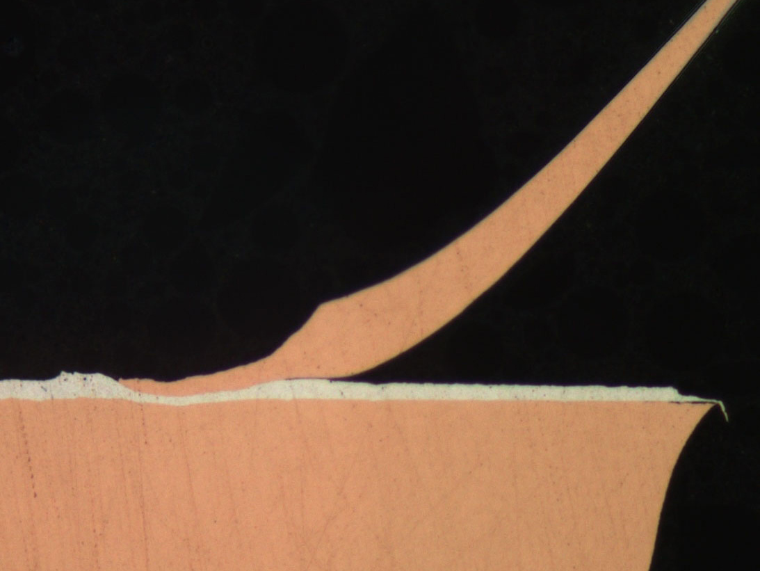
Cross-sectional view of secondary copper bond with acceptable effective bond area
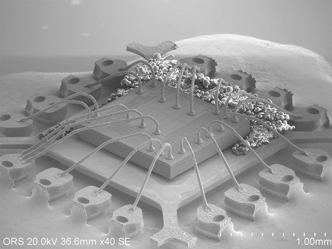
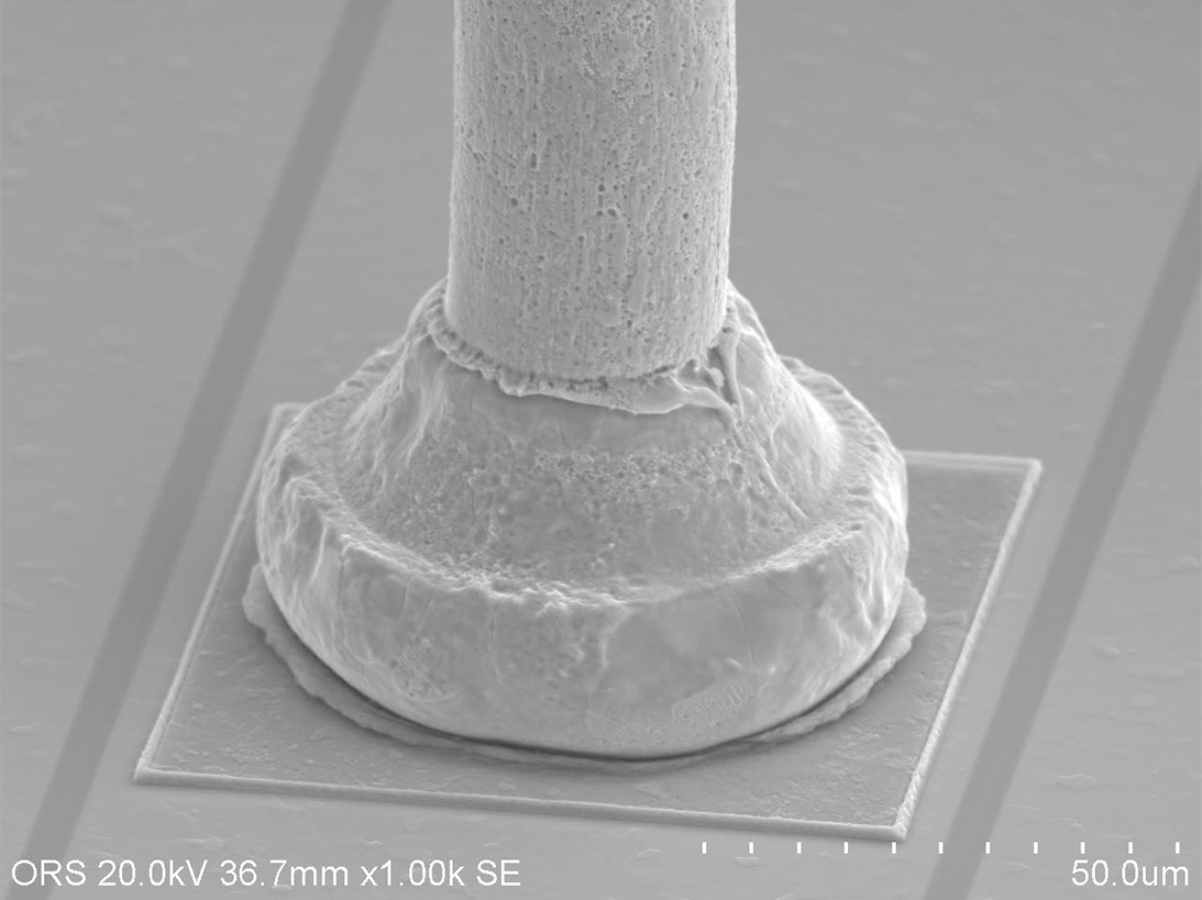
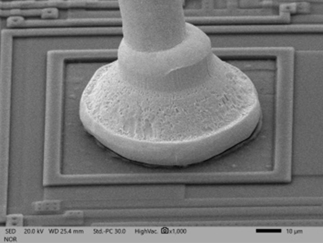
SEM image of de-encapsulated view of PEM with copper bond wires
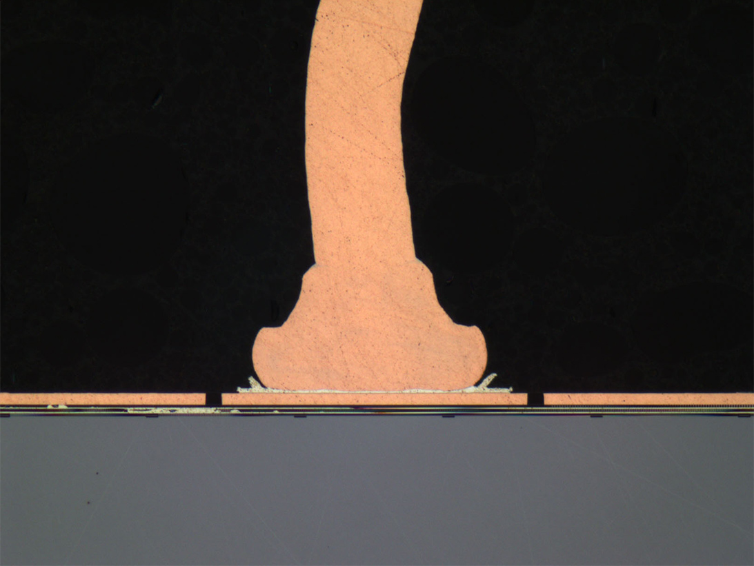
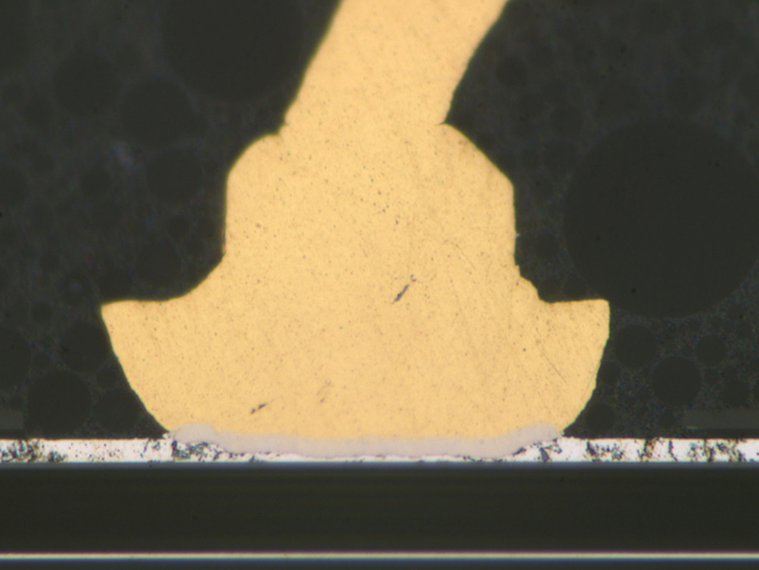
Optical cross-sectional view of Cu ball bond to aluminum over Cu
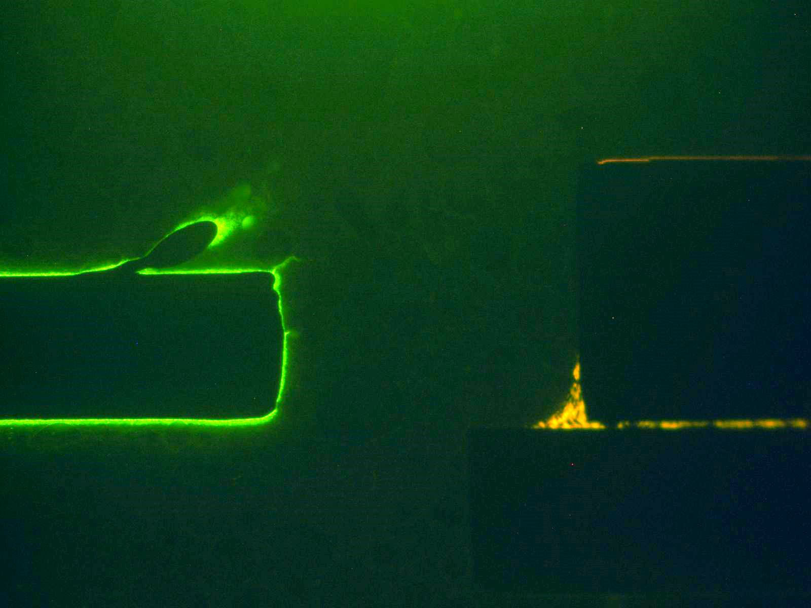
Fluorescent light micrograph of dye ingress to crescent bond
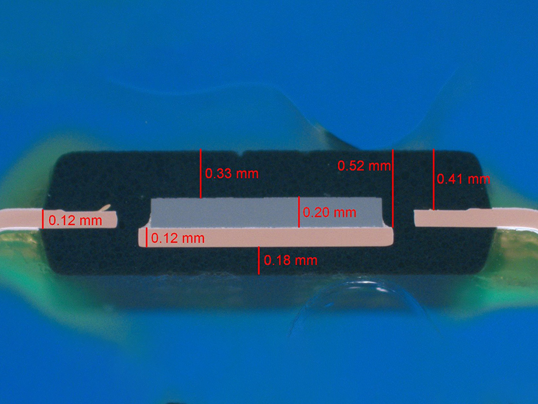
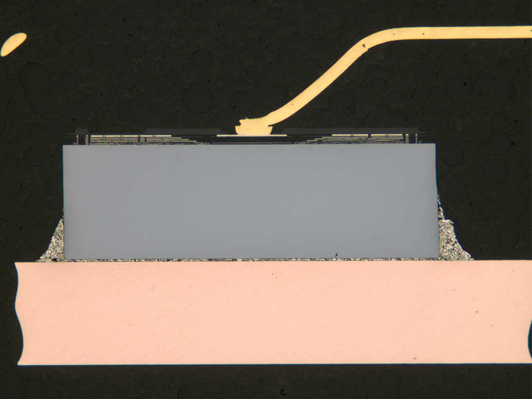
Optical cross-sectional image of PEM with internal physical dimensions
SEM image of copper ball bond to dye
SEM image of gold ball bond at dye
Cross-sectional view of Si dye and silver epoxy fillets with gold bond wire
Cross-sectional view of ball bond to aluminum pad IMC
Non-Destructive Test Methods
An important part of a DPA includes initial non-destructive test methods, including:
- External visual inspection (with physical dimensions/configuration compliance)
- X-ray radiography
- Acoustic microscopy
- Prohibited-material analysis performed by:
- Scanning electron microscopy with energy dispersive X-ray microanalysis (SEM/EDS)
- X-ray fluorescence elemental analysis (XRF)
- Fourier transform infrared microscopy (FTIR)*
*FTIR is commonly included in baseline DPA or Construction Analysis (CA) type analyses to document functional groups detected in mold compounds and other organic features (i.e., dye conformal coating and lead-frame adhesives).
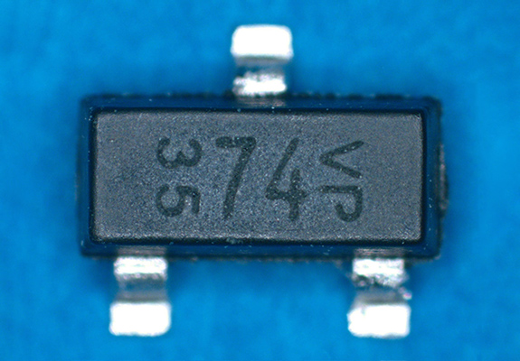
Optical image of SOT-23 depicting part markings device configuration and lead finish.
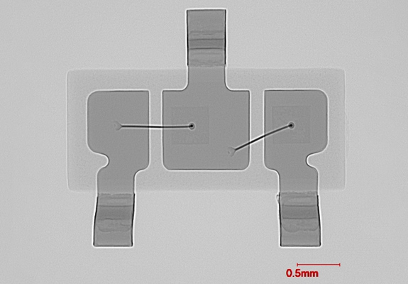
Digital radiograph image in the Y-axis of SOT-23, revealing dye placement, bond wire sweep and internal lead frame pattern.
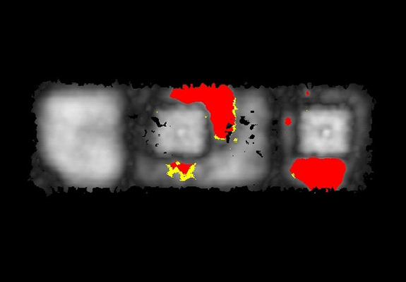
Acoustic image with phase inversion of the circuit-side EMC to dye and lead-frame delamination. Red areas indicate delaminated area.
Failure Modes* of PEM that can be revealed by DPA:
- EMC delamination/moisture sensitivity
- Wire bonding/intermetallic compound
- Copper wire bond issues including secondary bond corrosion
- Pure tin at external surfaces
- Undisclosed product changes
- Suspect counterfeit artifacts
*These vary based on construction and application
Applicable Industries:
- Space
- Aerospace
- Military Terrestrial
- Automotive/Commercial
- Mainframe Computers
Test Methods:
- MIL-STD-1580
- MIL-STD-883
- MIL-STD-750
- NASA PEM-INST-001
- IDEA STD-1010
- SAE-AS6294
- AEC-Q101
Summary of PEM Testing Methods:
- External Visual
- Physical Dimensions
- Lead Finish Verification
- X-ray Radiography
- Acoustic Microscopy
- Dye Impregnation
- Internal Visual Inspection
- De-encapsulation
- Cross-section
- Bond Strength Testing
- Bond Shear Testing
- SEM Metal Inspection
- Prohibited Materials Analysis

