Destructive Physical Analysis (DPA)
Testing for Connectors
Connectors are extremely important in military and space applications because they enable electronic components to communicate and work together. Although the construction of connectors may not be extremely complex, their repeated use and multiple points of connection require the highest manufacturing quality as they are critical for end-use assemblies.
Your Go-To Lab for Fast, Reliable Connector DPA
Connectors are important because they provide separable connections in electronic systems. When they connect components, they keep everything functioning. However, a latent failure can cause an unwanted error or system failure. Having ORS perform comprehensive testing on mission-critical connectors is vitally important in aerospace and defense.
Our comprehensive Destructive Physical Analysis (DPA) techniques are designed to identify any anomalies that can lead to field failure. DPA typically consists of non-destructive testing, mechanical testing, electrical testing and material analysis.
We perform Insulation Resistance and Dielectric Withstanding Voltage testing per the product specification and industry standards such as EIA to ensure the connector meets required electrical parameters.
Destructive Physical Analysis
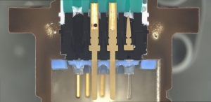
Typically, the destructive phase of testing includes cross sectioning or even shell removal to properly inspect passive internal components such as capacitors and diodes. We cross section connectors to be able to inspect and characterize the internal structure features of the component.
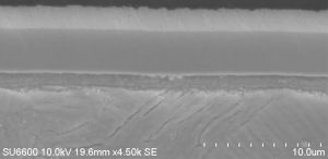
We examine the plating thickness and material identification of the shell and other plated parts at high magnification to ensure compliance to part or test specifications. This is important because the substrate of a connector shell is covered with a coating of a specific thickness and material type to protect the connector from corrosion or wear and tear. The coating can also provide heat resistance, chemical resistance and a means of electrical conductivity.
Contact us for information about connector testing
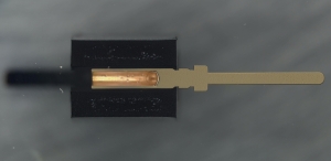
This is an optical image of a circular connector cross-sectioned halfway into its set of contacts. This allows for the inspection of internal features such as contact and insert placement or shell and contact plating thickness.
Socket and pin plating thicknesses can be verified with DPA. To conduct material analysis and verify plating thicknesses, contact is cross sectioned and plating layers are analyzed with a Scanning Electron Microscope (SEM).
This SEM image shows the plating layers of a typical contact after cross section and etching. In some cases, a wet etch technique is used to delineate plating layers, which allows for plating thickness measurements.
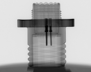
X-rays are ideal for inspecting internal connector features.
Non-Destructive Test Methods
As a part of DPA testing, ORS performs external visual examination and real time X-ray inspection. We perform external visual examination for configuration compliance to inspect for anomalies such as foreign material, plating defects, and chips or cracks of the inserts. We perform real-time X-ray inspection to identify issues with contact or insert seating or gross defects involving placement, cracks, breaks or missing parts.
Our mechanical testing typically includes tests such as plating adhesion, contact retention, insertion force and insulator retention. These tests may seem rudimentary but they yield valuable information regarding manufacturing quality.
Our electrical tests include insulation resistance and Hi-Pot testing. These tests are critical for verifying that electrical parameters are within specified tolerance. We perform Hi-Pot testing to check for sufficient insulation between individual contacts as well as between contacts and connector body and ground connections. We do insulation resistance testing to confirm that the specified resistance value is met or exceeded. These parameters are crucial to connector performance in the field.
Failure Modes of a Connector:
- Increased contact resistance, corrosion
- Insulation breakdown, increased contact resistance
- Damage to connector shell and key, mis-mating and circuit damage, excessive wear leading to intermittent or open connections
- Loose connections or jamming due to wear on threaded shells that are subject to repeated mating and un-mating
Typical Customers:
- Space
- Aerospace
- Military
Test Methods:
- EIA-364-20
- EIA-364-21
- EIA-364-29
- EIA-364-35
- ASTM B571-97
- SAE AMS-QQ-N-290
- SAE AMS-2454
- MIL-DTL-45204
- MIL-STD-202
- MIL-STD-1580, Requirement 11
Typical Connector Tests:
- External Visual
- Dimensions
- Clocking
- Electrical Test
- Hi-Pot Testing
- Insulation Resistance Testing
- X-Ray
- Insertion Force
- Contact Retention
- Insulator Retention
- Plating Adhesion
- External and Internal Prohibited Material Analysis
- Cross Section and/or Shell Removal
- Plating Thickness
- Internal Visual
- External Visual


